00193922-03.pdf - 第318页
7 Station extensions User manual SIPLA CE HF series 7.3 Component c amera for the TwinHead, FC came ra Software Version S R.50x.xx 01/ 2006 US Edition 318 7.3 Component ca mera for the T winHead, FC camera 7.3.1 S tructu…
User manual SIPLACE HF series 7 Station extensions
Software Version SR.50x.xx 01/2006 US Edition 7.2 Sensor for the component reject bin
317
7.2 Sensor for the component reject bin
Item no. 00116848-xx
The sensor for the component reject bin monitors whether the reject bin is seated correctly in its
mount.
– If the reject bin was not inserted correctly, the placement machine cannot be started.
– If the reject bin jumps out of its mount during the placement process, the machine is stopped
immediately to avoid a head crash.
Each reject bin can be monitored by a separate sensor.
7 Station extensions User manual SIPLACE HF series
7.3 Component camera for the TwinHead, FC camera Software Version SR.50x.xx 01/2006 US Edition
318
7.3 Component camera for the TwinHead, FC camera
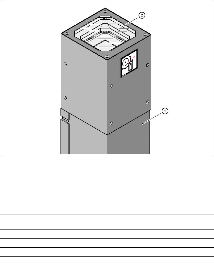
7.3.1 Structure of the component camera stationary P&P, type 20, 8 x 8 (FC camera)
Item no. 00119618-xx
7
Fig. 7.3 - 1 CO camera stationary P&P, type 20, 8 x 8 (FC camera)
(1) Camera housing with integral camera and camera amplifier
(2) Glass plate - over the illumination and lens levels
7.3.1.1 Technical data
7
Component dimensions 0.6 x 0.3 mm² up to 8 x 8 mm² for single component measurement
Range of components 0201 to SO, PLCC, QFP, sockets, plugs, BGA, special compo-
nents, bare dies, flip-chips, shields
Min. lead pitch 0.25 mm
Min. ball/bump diameter 0.08 mm
Field of vision 11 x 11 mm²
Method of illumination Front-lighting (6 levels, programable as required)
User manual SIPLACE HF series 7 Station extensions
Software Version SR.50x.xx 01/2006 US Edition 7.3 Component camera for the TwinHead, FC camera
319
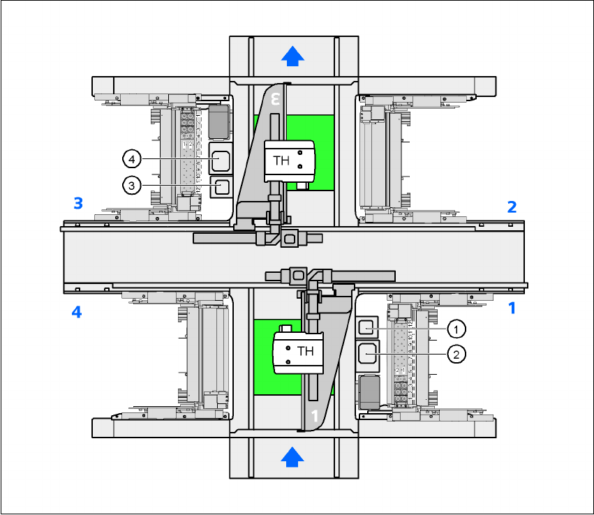
7.3.1.2 Position of the component vision cameras for the TwinHead on the
HF placement machine
7
Fig. 7.3 - 2 Position of the component vision cameras for the TwinHead on the HF placement machine
(1) Assembly position for the CO vision camera (stationary, P&P (type 20) 8 x 8), location 1
(2) Assembly position for the CO vision camera (stationary, P&P (type 22) 50 x 40), location 1
(3) Assembly position for the CO vision camera (stationary, P&P (type 20) 8 x 8), location 3
(4) Assembly position for the CO vision camera (stationary, P&P (type 22) 50 x 40), location 3