00193922-03.pdf - 第276页
6 Component handling User ma nual SIPLACE HF series 6.3 Component trolley Software Vers ion SR.50x.xx 01/2006 US Edition 276 6 6 6.3.3 Dimensi ons and cent er of grav ity 6 Fig. 6.3 - 4 Dimensions (all in millimeters) Th…

User manual SIPLACE HF series 6 Component handling
Software Version SR.50x.xx 01/2006 US Edition 6.3 Component trolley
275
Description of the modules 6
The chassis (item 1) runs smoothly and is easy to maneuver.
The handles (item 7) can be folded up or down.
The component feeder table (item 2) has a capacity of up to 15 locations for 30 mm wide feeder
modules. The feeder modules are mechanically centered on the table using centering pins and
centering balls. The feeder modules are supplied with compressed air via a separate compressed
air bar.
The interface for the power module, communication and safety circuits (item 6) is beneath the
component feeder table bed. The compressed air supply for bulk case feeder modules also
passes via this interface.
NOTE ON OPERATIONAL SAFETY
All component trolleys or matrix tray changers must be docked on the machine in order to oper-
ate it. If they are not, the machine stays in emergency stop status. The placement process is
interrupted.
The communication interface (item 3) supplies the necessary voltages and control signals to the
feeder modules.
In the standard version, the tape reel container (item 4) holds tape reels up to 17" (432 mm). The
pull-out waste tape container (item 5) can be found beneath the chassis. The cut waste tape travel
down a chute into the waste container, which must be regularly emptied.
6.3.2 Technical data
6
Length x width
727.5 x 592 mm²
751.5 x 592 mm² with waste container
Height
829.5 mm for 830 mm PCB transport height
899.5 mm for 900 mm PCB transport height
929.5 mm for 930 mm PCB transport height
949.5 mm for 950 mm PCB transport height
PCB transport height
830 mm ± 15 mm (standard)
900 mm ± 15 mm (SMEMA)
930 mm ± 15 mm (SMEMA)
950 mm ± 15 mm (SMEMA)
Weight
Without feeder modules
With feeder module at all locations
With compressed air supply for bulk case
feeder module and adapter for 3rd tape reel
Approx. 85 kg
Approx. 125 kg
Approx. 150 kg
6 Component handling User manual SIPLACE HF series
6.3 Component trolley Software Version SR.50x.xx 01/2006 US Edition
276
6
6
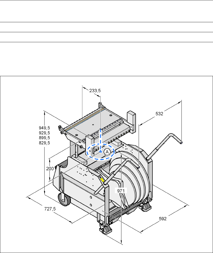
6.3.3 Dimensions and center of gravity
6
Fig. 6.3 - 4 Dimensions (all in millimeters)
The center of gravity (A) of the component trolley was determined under the following conditions:
– Component trolley set to a PCB transport height of 830 mm.
Reel diameter
Standard
Maximum
Up to 432 mm (17")
483 mm (19")
Feeder module locations Max. 15
Changeover time for the component trolley Less than 1 min.
User manual SIPLACE HF series 6 Component handling
Software Version SR.50x.xx 01/2006 US Edition 6.3 Component trolley
277
6.3.4 Tape container
The tape container can hold reels up to 19" in diameter. You should use spindles to process reels
of 15" diameter or more. The use of separating plates is described in section 5.3
on page 229.
PLEASE NOTE
For optimum operation, we recommend the use of spindles for 15" diameter or more.
6
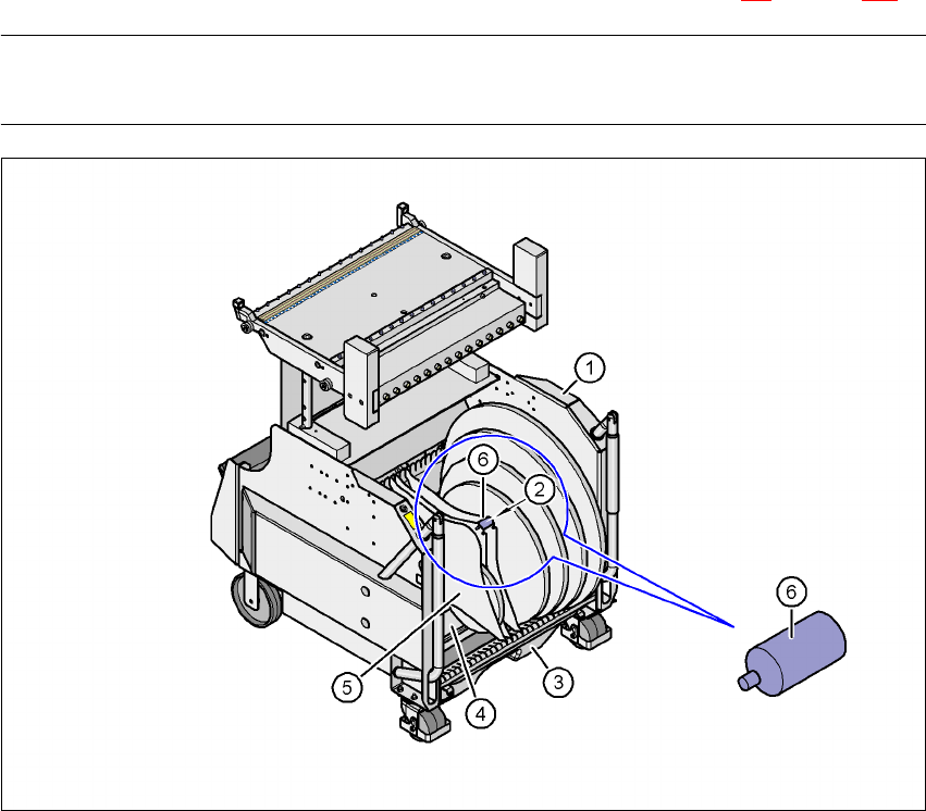
Fig. 6.3 - 5 Component trolley with tape container
(1) Component trolley
(2) Position of the spindles
(3) Waste tape container
(4) Tape container
(5) Separating plate
(6) Spindle (enlarged)