00193922-03.pdf - 第87页
User manual SIPLAC E HF series 2 Operational safety Software Vers ion SR.50x.xx 01/2006 US Edition 2.10 Lock out and tag out procedure 87 Fig. 2.10 - 2 Locking the motor contactor 2 – The tag out a lternative: If a machi…
2 Operational safety User manual SIPLACE HF series
2.10 Lock out and tag out procedure Software Version SR.50x.xx 01/2006 US Edition
86
Æ Isolate the machine from all its energy sources:
– Shut off the compressed air supply
– Shut off the main power supply
Æ Lock out the machine.
– Attach a lock whenever possible, e.g. to the motor contactor.
2
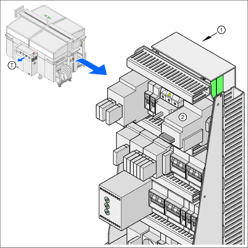
Fig. 2.10 - 1 Position of the motor contactor
2
(1) Power supply
(2) Motor contactor
(T) Direction of PCB transport
User manual SIPLACE HF series 2 Operational safety
Software Version SR.50x.xx 01/2006 US Edition 2.10 Lock out and tag out procedure
87
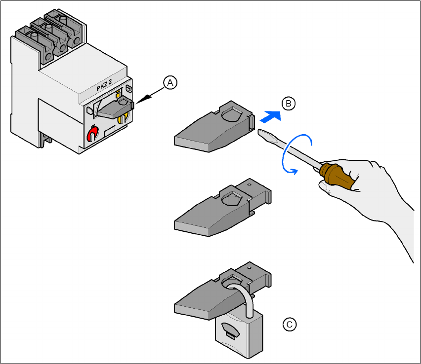
Fig. 2.10 - 2 Locking the motor contactor
2
– The tag out alternative:
If a machine can be locked out, it must be. However, there are situations where energy
isolating devices cannot accommodate locks. In these cases, the energy isolating de-
vices must be tagged to warn employees that the machine is de-energized for servicing.
The tag must be securely fastened, it must be placed in a position visible to all and it
may only be removed by the person who attached it. 2
Æ Release stored energy
(A) Turn the operating lever counterclockwise.
(B) Use the screwdriver to push the locking lug out of the operating lever.
(C) Secure the operating lever with a padlock.

2 Operational safety User manual SIPLACE HF series
2.10 Lock out and tag out procedure Software Version SR.50x.xx 01/2006 US Edition
88
Stored energy in the compressed air supply or electrical energy in electrolytic capacitors must
be released by appropriate means. 2
– After switching off the placement machine wait until the voltages and the compressed air
have discharged (see Sections 2.7
and 2.8), to be able work without any risk.
Æ Verify the lock out.
Testing the lock out can be done simply by pressing the start button.
Æ The following steps must be taken to restore the machine to operation.
Æ Check the area. Authorized employees should remove all of their tools and reinstall all
guards.
Æ Notify all affected employees.
Æ Before removing even one lock or tag, inform all workers in the area that the machine is going
to be restarted.
Æ Remove locks/tags
Æ Each authorized employee must remove his or her own lock. Each authorized employee will
have his or her own lock.
Æ Turn the machine on. Authorized workers should observe the equipment in operation to in-
sure repairs were done correctly.
2.10.3 Testing
The maintenance or electrical person may test the circuits by energizing the circuit for a short pe-
riod of time without voiding the lock out procedure provided. This may be done only when no other
work is being performed by any other person on the equipment being tested.
It is extremely important that all remote start switches be tagged with the Do Not Operate tag to
prevent inadvertent operation of the equipment during these periods.
2.10.4 Responsibilities
– It shall be the responsibility of the maintenance and electrical personnel to make sure this pro-
cedure is adhered to.
– It shall be the responsibility of the maintenance and electrical personnel’s immediate super-
visor to instruct his personnel on this procedure.
– It shall be the responsibility of the Safety Officer with assistance from the Safety Committee,
Health Service Department, and the various managers and Vice-presidents to administer the
Lock Out / Tag Out Procedure.