00193922-03.pdf - 第155页
User manual SIPLAC E HF series 3 Technical data Software Vers ion SR.50x.xx 01/2006 US Edition 3.13 Flexible dual P CB conveyor 155 3.13.3 Description of the funct ions The flex ible dua l conve yor has two conv eyor tra…

3 Technical data User manual SIPLACE HF series
3.13 Flexible dual PCB conveyor Software Version SR.50x.xx 01/2006 US Edition
154
3.13.2 Technical data
3
Fixed conveyor side Right or left
PCB format
Standard (length x width)
"Wide board" configuration
Long board option
Long board option and "Wide board"
configuration
Dual conveyor in "Single conveyor" mode
Standard (length x width)
"Wide board" configuration
Long board option
Long board option and "Wide board"
configuration
50 x 50 mm² to 450 x 216 mm² (item no. 00119627-xx)
50 x 50 mm² to 450 x 250 mm² (item no. 00119629-xx)
50 x 80 mm² to 610 x 216 mm² (item no. 00119672-xx)
50 x 80 mm² to 610 x 250 mm²
50 x 50 mm² to 450 x 380 mm²
50 x 50 mm² to 450 x 450 mm²
50 x 80 mm² to 610 x 380 mm²
50 x 80 mm² to 610 x 450 mm²
PCB thickness
Standard 0.3 mm to 4.5 mm ± 0.2 mm
(thicker PCBs available on request)
Max. PCB warpage Up: 6 mm - PCB thickness
Down: 0.3 mm + PCB thickness
PCB weight Max. 3 kg
Clearance on PCB underside
Standard
Option
25 mm ± 0.2 mm
Max. 40 mm ± 0.2 mm
PCB transport height 830mm ± 15mm (standard)
900mm ± 15mm (optional)
930mm ± 15mm (optional)
950mm ± 15mm (SMEMA: optional)
Type of interface SMEMA / SIEMENS
Component-free PCB handling edge 3 mm
PCB changeover time < 2.5 s
PCB positioning accuracy ± 0.5 mm
Conveyor mode Synchronous or asynchronous
Components on each conveyor Same or different
PCB width on each conveyor Same or different
Bad fiducial detection Synchronous: impossible, asynchronous: possible
Automatic width adjustment Synchronous: possible, asynchronous: possible
User manual SIPLACE HF series 3 Technical data
Software Version SR.50x.xx 01/2006 US Edition 3.13 Flexible dual PCB conveyor
155
3.13.3 Description of the functions
The flexible dual conveyor has two conveyor tracks that are electrically and mechanically inde-
pendent of one another. The functions are the same as for the single conveyor (see Section
3.12.3
, page 151. 3
3.13.4 "Flexible dual conveyor" performance feature
The "flexible dual conveyor" performance feature allows the conveyor track to be widened be-
yond the standard width of 216 mm. Over-wide PCBs can then be processed in a machine with
a dual conveyor. The side walls of the second conveyor track are moved fully together, which
deactivates the conveyor track at the same time. 3
3
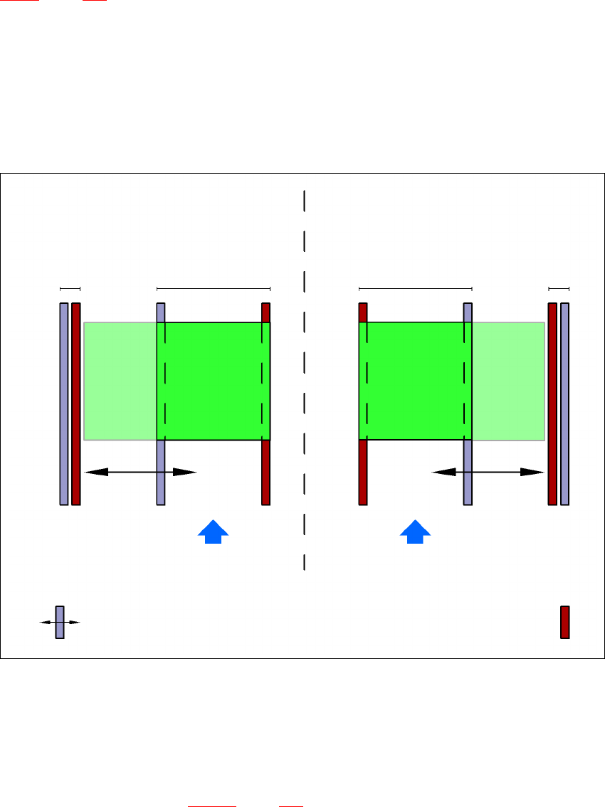
Fig. 3.13 - 2 Flexible dual conveyor in Single conveyor mode
3
3
3.13.5 Defining the conveyor tracks
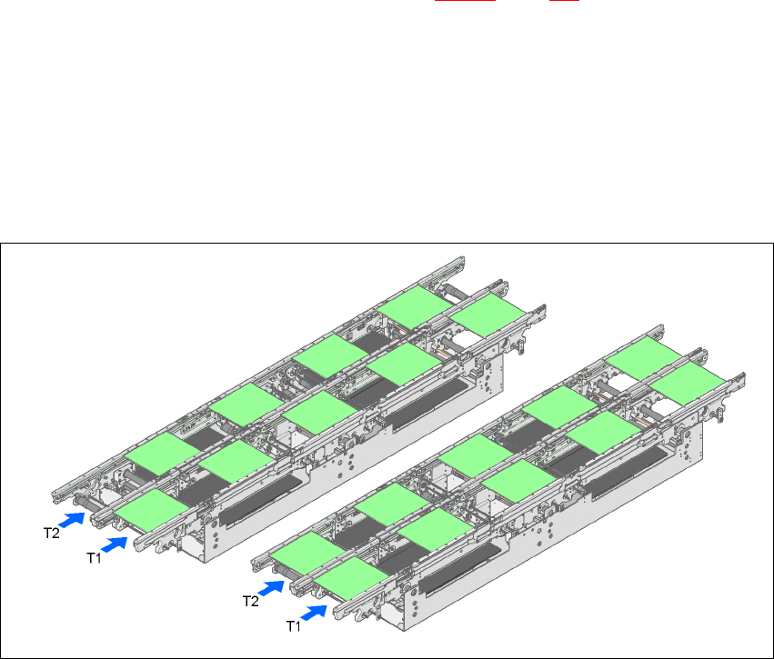
The right conveyor track (viewed in the transport direction) is designated "Conveyor 1" and the
left as "Conveyor 2" (see Fig. 3.13 - 3
, page 156). 3
Dual conveyor with widened conveyor track 2
(stationary conveyor side wall on left)
Conveyor track 2
deactivated
Conveyor track 1 Conveyor track 2 Conveyor track 1
deactivated
PCB transport direction PCB transport direction
Stationary conveyor side wall
Dual conveyor with widened conveyor track 1
(stationary conveyor side wall on right)
Movable conveyor side wall
3 Technical data User manual SIPLACE HF series
3.13 Flexible dual PCB conveyor Software Version SR.50x.xx 01/2006 US Edition
156
3.13.6 Definition of the conveyor track width
3.13.6.1 Standard width
The standard width of the conveyor track is the maximum conveyor width defined by the desired
position of the stationary conveyor side. It is no more than 216 mm per track. 3
3.13.6.2 Overwide conveyor track
The conveyor track can be widened to 250 mm maximum by moving the stationary conveyor side
wall out of its normal position. 3
3.13.6.3 Dual conveyor in Single conveyor mode
The dual conveyor can be configured online to create a single conveyor. To do this, one conveyor
track is moved fully together and deactivated (see Fig. 3.13 - 2
, page 155). This gives a conveyor
track width of up to 450 mm. 3
3.13.7 Transport modes
The flexible dual conveyor can be used in two modes: 3
– Synchronous transport mode
– Asynchronous transport mode
3
Fig. 3.13 - 3 Transport modes
Synchronous
transport mode
Asynchronous
transport mode