00193922-03.pdf - 第283页
User manual SIPLAC E HF series 6 Component handling Software Vers ion SR.50x.xx 01/2006 US Edition 6.5 Remov ing the used tape channel div iding plate 283 6.5 Remov ing the used tape channel dividing plate In the standar…
6 Component handling User manual SIPLACE HF series
6.4 Used tape chute, SIPLACE HF Software Version SR.50x.xx 01/2006 US Edition
282
6.4 Used tape chute, SIPLACE HF
6
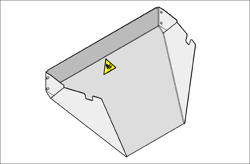
Fig. 6.4 - 1 Used tape chute for SIPLACE HF
The used tape chute for the SIPLACE HF is attached to the component trolley docking unit. The
waste tape that is chopped up by the tape cutter slides onto the used tape chute and into the waste
container of the component trolley.
User manual SIPLACE HF series 6 Component handling
Software Version SR.50x.xx 01/2006 US Edition 6.5 Removing the used tape channel dividing plate
283
6.5 Removing the used tape channel dividing plate
In the standard version, the used tape channel can guide component tapes with a maximum
pocket height of 17 mm to the pneumatic tape cutter.
6
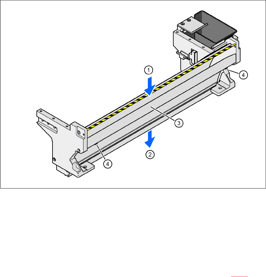
Fig. 6.5 - 1 Used tape channel with component reject bin
(1) Inlet slot for the used tapes
(2) Outlet slot for the used tape above the pneumatic tape cutter
(3) Dividing plate for tapes < 17 mm (can be removed for tapes > 17 mm)
(4) DIN 84 - M3x6 screw, 2x
If feeder modules that process component tapes with a pocket height > 17 mm are used, such as,
for example, the 44 mm S DP feeder module, then the separating plate (item 3 in Fig. 6.5 - 1
) must
be removed.
6 Component handling User manual SIPLACE HF series
6.5 Removing the used tape channel dividing plate Software Version SR.50x.xx 01/2006 US Edition
284
WARNING 6
Æ Switch the placement machine off at the main switch to remove the dividing plate.
Æ Disconnect the machine from the power and compressed air supply.
Æ Secure the machine to prevent it being switched on again, as described in section 2.10, page
85
.
Æ Wait until the operating pressure for the tape cutter has dropped to 0 MPa.
Æ Wear robust protective gloves.
Æ Do not reach inside the used tape channel.
Æ Loosen the two slotted screws (item 4 in Fig. 6.5 - 1).
Æ Pull out the dividing plate.
PLEASE NOTE
Do not position feeder modules with shallow pockets immediately beside bar feeder modules
with deep pockets. The used tapes could overlap and build up.