00193922-03.pdf - 第118页
3 Technical data User manual SIPLACE HF series 3.7 Placement heads S oftware Version SR.50x.x x 01/2006 US Edition 118 3.7.2 12-se gment Collect &Place hea d for high-speed placeme nt 3 Fig. 3.7 - 3 12-segment Collec…
User manual SIPLACE HF series 3 Technical data
Software Version SR.50x.xx 01/2006 US Edition 3.7 Placement heads
117
When you order a SIPLACE HF or HF/3 placement system, you can select the ideal head config-
uration for your needs. The placement machine will be configured and supplied as per your order.3
There is also a reconfiguration kit if you wish to change the placement head locally. This package
contains the necessary assembly parts, cables, etc., in addition to the placement head. 3
Before changing the placement head, you should first adapt the station and SIPLACE Pro soft-
ware. The system will then have to be recalibrated. 3
Head modularity, i.e. adapting the placement machine to the production requirements by changing
the placement head, has the advantage that it is an easy way to match the placement machine to
your production needs without having to invest in further machines. 3
3 Technical data User manual SIPLACE HF series
3.7 Placement heads Software Version SR.50x.xx 01/2006 US Edition
118
3.7.2 12-segment Collect&Place head for high-speed placement
3
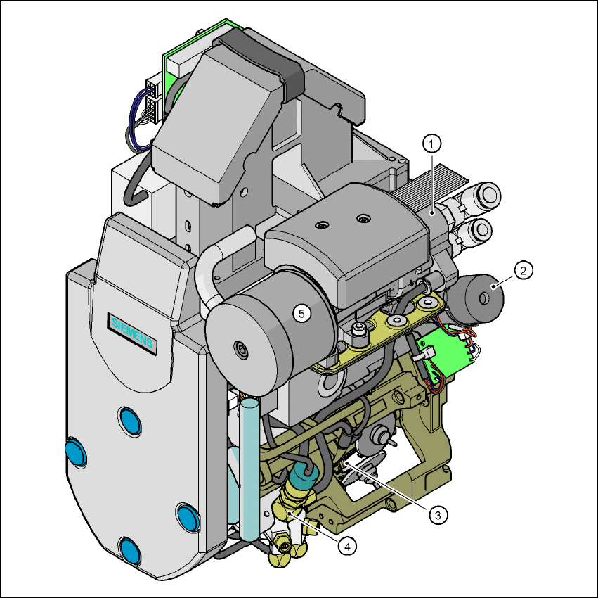
Fig. 3.7 - 3 12-segment Collect&Place head - Function groups, part 1
3
(1) Vacuum generator
(2) Turning station, DP axis
(3) Star with 12 sleeves, star axis
(4) Forced air valve
(5) Silencer
User manual SIPLACE HF series 3 Technical data
Software Version SR.50x.xx 01/2006 US Edition 3.7 Placement heads
119
3
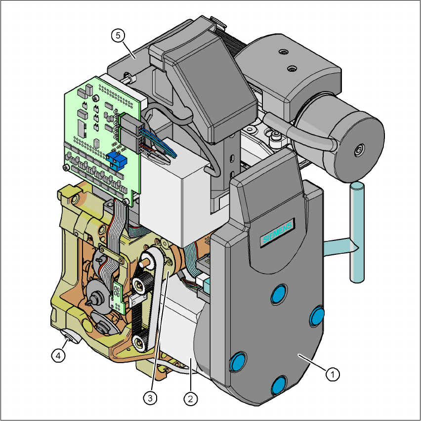
Fig. 3.7 - 4 12-segment Collect&Place head - Function groups, part 2
3
(1) Intermediate distributor board (beneath the cover)
(2) Star drive - DR motor
(3) Z axis motor
(4) Valve adjustment drive
(5) 24 x 24 component vision camera
3
3.7.2.1 Description
The 12-segment Collect&Place head works on the Collect&Place principle. This means that,
within each cycle, twelve components are picked up by the placement head, are optically cen-
tered on the way to the placement position and are rotated into the required placement angle.