00193922-03.pdf - 第143页
User manual SIPLAC E HF series 3 Technical data Software Vers ion SR.50x.xx 01/2006 US Edition 3.10 Gantries 143 The Y axis es sential ly co nsis ts of the foll owing mai n modules : 3 – Y -a xis linea r mo tor (pri ma r…
3 Technical data User manual SIPLACE HF series
3.10 Gantries Software Version SR.50x.xx 01/2006 US Edition
142
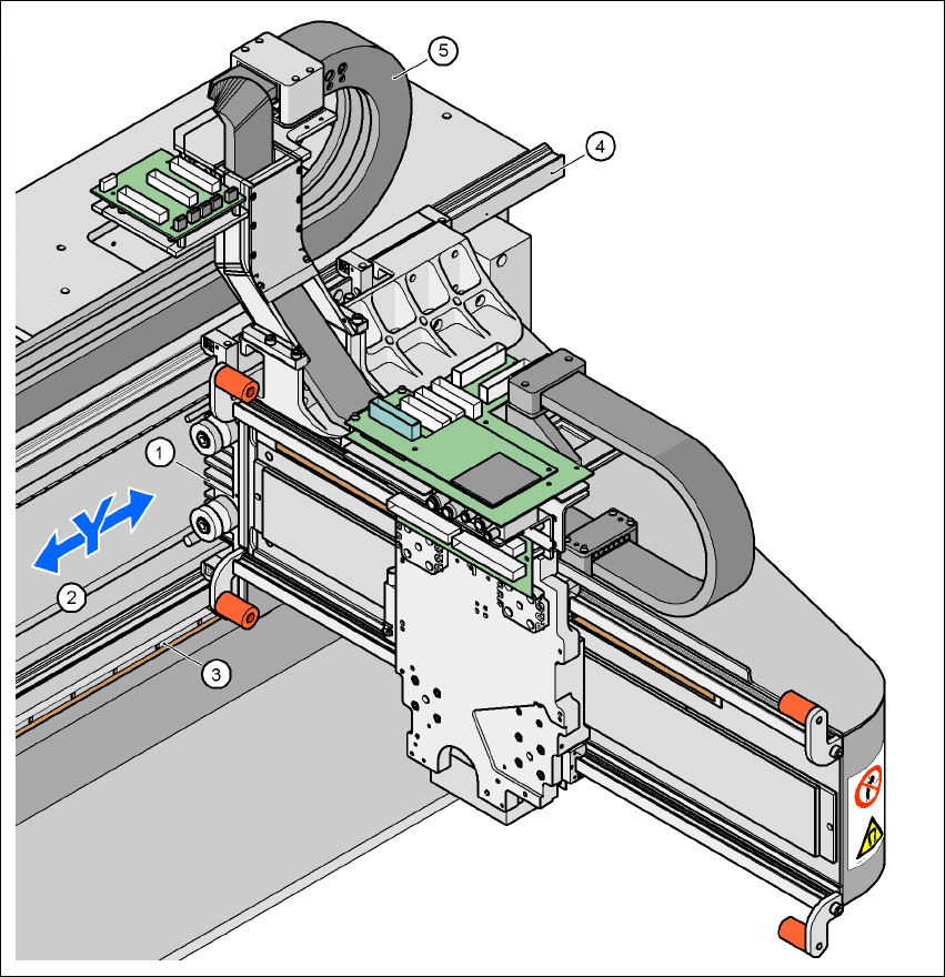
3.10.5 Structure of the Y axis
3
Fig. 3.10 - 4 Structure of the Y axis
3
(1) Y-axis linear motor (primary part)
(2) Permanent magnet (secondary part of the Y-axis linear motor)
(3) Linear distance measuring system
(4) Guide system
(5) Cable and hose carrier

User manual SIPLACE HF series 3 Technical data
Software Version SR.50x.xx 01/2006 US Edition 3.10 Gantries
143
The Y axis essentially consists of the following main modules: 3
– Y-axis linear motor (primary part) (1)
– Permanent magnet (secondary part of the Y-axis linear motor) (2)
– Linear distance measuring system (3)
– Guide system (4)
– Cable and hose carrier (5)
3
The Y axis is driven by a linear motor. The secondary part of the drive is made up of permanent
magnets and is mounted on the machine frame. The primary part is bolted to the gantry. 3
3.10.6 Technical data for the Y axis
3
Drive Direct, linear motor
Maximum speed 2.5 m/sec.
Traversing path 1430 mm
Distance measuring system Metal linear scale
Scale length 1850 mm
Resolution 1 µm
3 Technical data User manual SIPLACE HF series
3.11 Vision modules Software Version SR.50x.xx 01/2006 US Edition
144
3.11 Vision modules
Every 6-segment and every 12-segment Collect&Place head has a separate component vision
module (see Fig. 3.7 - 3
page 118 and Fig. 3.7 - 6 page 123). The stationary P&P component vi-
sion camera (type 22) 50 x 40 is permanently fixed to the machine frame. 3
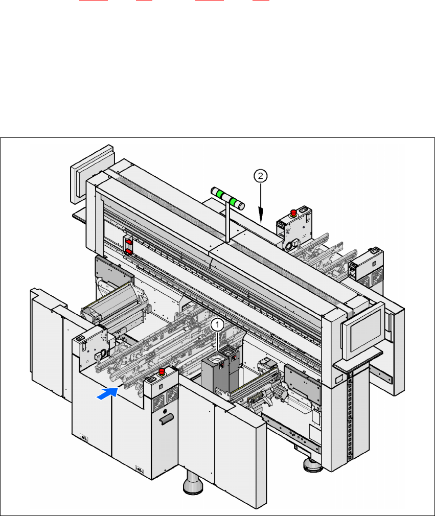
Assembly positions for the stationary P&P component vision camera (type 22) 50 x 40 3
3
3
Fig. 3.11 - 1 Assembly positions for the stationary P&P component vision camera (type 22) 50 x 40
3
(1) Assembly position for location 1 (HF placement machine)
(2) Assembly position for location 3 (HF and HF/3 placement machine)
TwinHead Stationary P&P component vision camera (type 22) 50 x 40
Placement area 1 Location 1 (HF placement machine)
Placement area 2 Location 3 (HF and HF/3 placement machine)