00193922-03.pdf - 第244页
5 Tasks on the machine User manual SIPLACE HF series 5.9 Note operating status indicator lamp Software Vers ion SR.50x.xx 01/2006 US Edition 244 5.9 Note operating st atus indicator lamp The ind icator lam p is us ed to …
User manual SIPLACE HF series 5 Tasks on the machine
Software Version SR.50x.xx 01/2006 US Edition 5.8 Docking the component trolley in or out
243
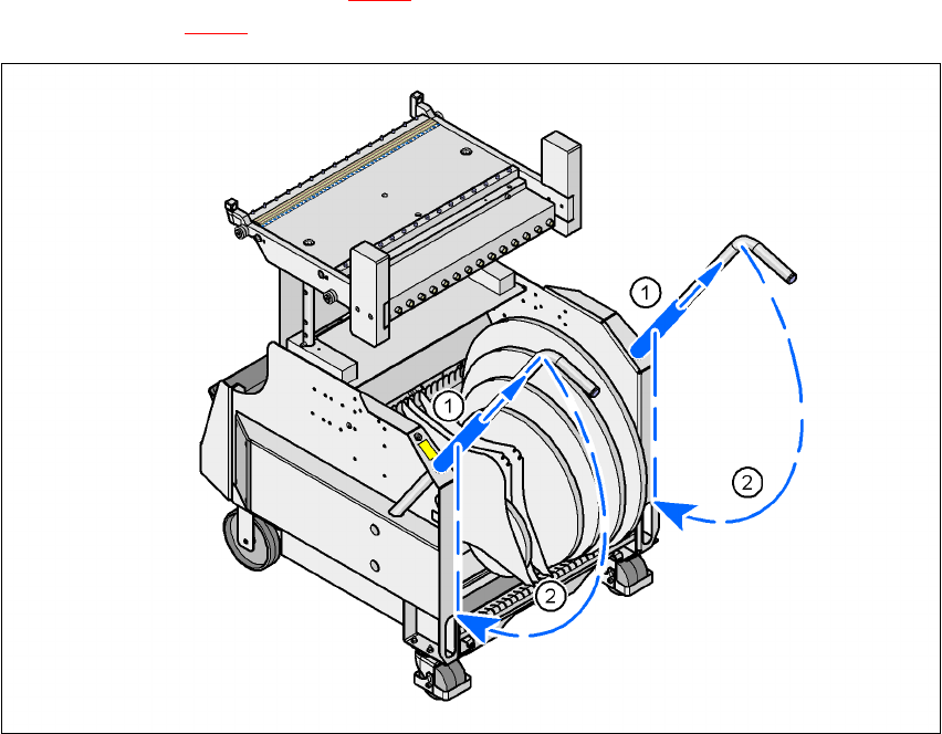
Æ Push the sleeve (item 1 in Fig. 5.8 - 2) up using both handles and swivel the handle down
(item 2 in Fig. 5.8 - 2
).
5
Fig. 5.8 - 3 Component trolley - Swivel handles down
(1) Push sleeve up
(2) Fold handle down
5 Tasks on the machine User manual SIPLACE HF series
5.9 Note operating status indicator lamp Software Version SR.50x.xx 01/2006 US Edition
244
5.9 Note operating status indicator lamp
The indicator lamp is used to signal operating statuses and malfunctions of the placement system.
5.9.1 Description of the functions
5
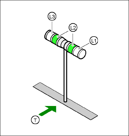
Fig. 5.9 - 1 Operating status indicator lamp
L1 Fault indicator lamp (white, right)
L2 Operating status indicator lamp (green, both lamps switched in parallel)
L3 Fault indicator lamp (white, left)
T Direction of PCB transport
5.9.2 General operating statuses
–
Operating status indicator lamp (green) on continuously
The placement system is in service.
–
Operating status indicator lamp (green) flashes
The placement system is waiting for a PCB on the input belt or the placement system is wait-
ing until the output belt is free.
–
Right white fault indicator lamp L1 flashes
One or more tracks are empty on the right-hand side of the placement system. The placement
system continues to place any remaining components.

User manual SIPLACE HF series 5 Tasks on the machine
Software Version SR.50x.xx 01/2006 US Edition 5.9 Note operating status indicator lamp
245
–
Left white fault indicator lamp L3 flashes
One or more tracks are empty on the left-hand side of the placement system. The placement
system continues to place any remaining components.
–
Right white fault indicator lamp (L1) on continuously - green operating status lamp (L2) off
An error has occurred on the right-hand side of the placement system -> the placement sys-
tem has stopped.
–
Left white fault indicator lamp (L1) on continuously - green operating status lamp (L2) off
An error has occurred on the left-hand side of the placement system -> the placement system
has stopped.
–
Both white fault indicator lamps (L1 and L3) on continuously - green operating status lamp off
An error has occurred that affects the entire placement system -> the placement system has
stopped.
5.9.3 Programmed operating status displays
The following table shows the programmed operating status displays in the standard configuration
(version as supplied) and lists their meaning on the individual lamps of the main fault indicator.
The entries in the table next to "flashes" refer to the frequency with which the relevant lamp flashes
for a given event. The entry (1, 5), for example, can be explained as follows:
– The first number in the brackets indicates the time, expressed in 100 msec intervals, for which
the fault indicator lamp is switched on, i.e. 1 x 100 msec in the above example.
– The second number in the brackets indicates the time, expressed in 100 msec intervals, for
which the fault indicator lamp is switched off, i.e. 5 x 100 msec in the above example.
5
L1 (white)
(right lamp)
L2 (green) L3 (white)
(left lamp)
Meaning
Status display
flashes (1, 10) flashes (7, 7) flashes (1, 10) Reference run
unchanged flashes (1, 5) unchanged Waiting until axes in position
unchanged flashes (7, 7) unchanged Waiting for setup data
unchanged flashes (7, 7) unchanged Waiting for cluster data
unchanged flashes (7, 7) unchanged Load table program
unchanged flashes (7, 7) unchanged Position detection
unchanged flashes (1, 10) unchanged Bad fiducial detection
unchanged flashes (7, 7) unchanged Nozzle configuration test
unchanged flashes (7, 7) unchanged Feeder position detection
unchanged flashes (7, 7) unchanged One track is empty
unchanged flashes (7, 7) unchanged No further track available