00193922-03.pdf - 第334页
7 Station extensions User manual SIPLA CE HF series 7.8 PCB alignment Software Version S R.50x.xx 01/2006 US Edition 334 7.8 PCB alignment Item no. 001 1967 7-xx PCB alignmen t for sin gle convey or Item no. 001 1967 8-x…

User manual SIPLACE HF series 7 Station extensions
Software Version SR.50x.xx 01/2006 US Edition 7.7 SIPLACE High-Force Head
333
7.7 SIPLACE High-Force Head
Item no. 00119634-xx High-Force Head for the HF series (rather than a TwinHead)
This item number only applies when a new placement machines is ordered with a High-Force
Head rather than a standard TwinHead. 7
Item no. 00119753-xx High-Force upgrade kit
Use this item number if you want to replace a standard TwinHead with a High-Force Head.7
Item no. 00119654-xx High-Force Head reconfiguration kit
Use this item number if you want to replace a Collect&Place head with a High-Force Head.7
7.7.1 General
The SIPLACE High-Force Head is a development offshoot of the standard TwinHead. It can pro-
cess the same component range and also offers the possibility of achieving set-down forces up to
30 N.
Otherwise the technical data for the TwinHead and High-Force Head is the same (see section
3.7.4.3
, page 131).
All the nozzles and grippers that are used with the standard TwinHead can be used for the SI-
PLACE High-Force Head.
Programmable set-down force 1 N to 1.8 N ± 0.18 N
1.8 N to 10 N ± 10 %
greater than 10 N up to 30 N ± 15 %
7 Station extensions User manual SIPLACE HF series
7.8 PCB alignment Software Version SR.50x.xx 01/2006 US Edition
334
7.8 PCB alignment
Item no. 00119677-xx PCB alignment for single conveyor
Item no. 00119678-xx PCB alignment for dual conveyor
7.8.1 General
PCBs to be processed sometimes have a length to width ratio of 1:2 or worse. This means that
the shorter side of the PCB points in the direction of travel. During travel, such PCBs may twist
slightly and, as a result, the fiducials no longer lie within the PCB vision camera's search window.
In this case, the "PCB alignment" option ensures that these PCBs are realigned precisely at the
stopping position.
If PCBs with recesses in the direction of travel are processed, this may result in different process-
ing positions on machines with mechanical stoppers (HS-50, S-25 HM, F5 HM) and on machines
that monitor this position with laser light barriers (HF, HS-60, S-27 HM). The "PCB alignment" op-
tion ensures that the PCBs are stopped at the same position on all PCB conveyors. The "PCB
alignment" option is available for both single and dual conveyors.
7
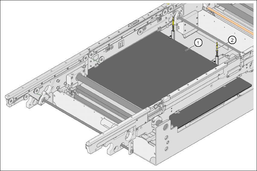
Fig. 7.8 - 1 PCB alignment
(1) Lifting table
(2) PCB stop
User manual SIPLACE HF series 7 Station extensions
Software Version SR.50x.xx 01/2006 US Edition 7.8 PCB alignment
335
7.8.2 Description of the functions
The PCB is transported into the placement area until the laser light barrier triggers the stop signal
for the PCB conveyor. The lifting table with the PCB stops then moves up into a position in which
the PCB is not yet clamped and can still be moved by the conveyor belts. The two PCB stops are
level with the PCB, and the PCB supports (magnetic pins) are already in contact with the PCB.
The two conveyor belts move the PCB against the PCB stops and align them at the same time.
The lifting table then moves into its top end position, clamps the PCB and releases it from the PCB
stops so as not to affect the placement process. After the placement process, the lifting table and
PCB alignment are lowered and the PCB is moved on.
7