00193922-03.pdf - 第243页
User manual SIPLAC E HF series 5 T asks on the m achine Software Vers ion SR.50x.xx 01/2006 US Edition 5.8 Docking the com ponent trolley in or out 243 Æ P ush the s leeve ( item 1 in Fig. 5.8 - 2 ) up using both han dle…
5 Tasks on the machine User manual SIPLACE HF series
5.8 Docking the component trolley in or out Software Version SR.50x.xx 01/2006 US Edition
242
5.8.3 Safety instructions for moving the component trolley
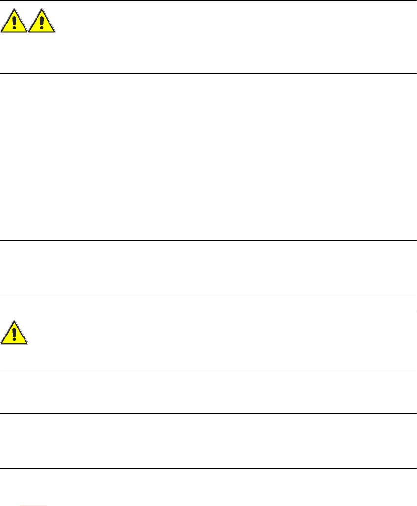
WARNING
To prevent accidents, ALWAYS follow the rules listed below when you move the component trol-
ley.
Æ Always hold the handles with both hands when you want to move the component trolley.
Æ Remember that a component trolley with the full complement of feeder modules can tip over
sideways or forward on gradients of 20° or more.
Æ Make sure that the surface on which the trolley is moved has a significantly smaller gradient.
Æ Be careful not to collide with obstacles. The trolley could tip forward if it is traveling fast
enough.
5.8.4 Docking in the component trolley
PLEASE NOTE
Shorten the component tapes on the front end of the S feeder to approximately 3 cm before you
dock in the component trolley.
CAUTION
Check that the placement head is outside the range of the component trolley.
Æ Carefully push the component trolley into machine as far as the stop.
PLEASE NOTE
Close the protective covers since the component trolley can only be docked in if the covers are
closed.
Æ Press the relevant button on the input or output side of the machine (item 1, 2, 3 or 4 in Fig.
5.8 - 1
) until the trolley is docked in fully.
User manual SIPLACE HF series 5 Tasks on the machine
Software Version SR.50x.xx 01/2006 US Edition 5.8 Docking the component trolley in or out
243
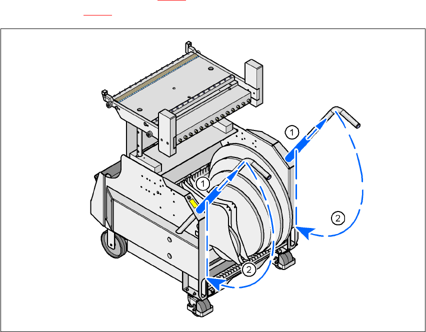
Æ Push the sleeve (item 1 in Fig. 5.8 - 2) up using both handles and swivel the handle down
(item 2 in Fig. 5.8 - 2
).
5
Fig. 5.8 - 3 Component trolley - Swivel handles down
(1) Push sleeve up
(2) Fold handle down
5 Tasks on the machine User manual SIPLACE HF series
5.9 Note operating status indicator lamp Software Version SR.50x.xx 01/2006 US Edition
244
5.9 Note operating status indicator lamp
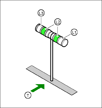
The indicator lamp is used to signal operating statuses and malfunctions of the placement system.
5.9.1 Description of the functions
5
Fig. 5.9 - 1 Operating status indicator lamp
L1 Fault indicator lamp (white, right)
L2 Operating status indicator lamp (green, both lamps switched in parallel)
L3 Fault indicator lamp (white, left)
T Direction of PCB transport
5.9.2 General operating statuses
–
Operating status indicator lamp (green) on continuously
The placement system is in service.
–
Operating status indicator lamp (green) flashes
The placement system is waiting for a PCB on the input belt or the placement system is wait-
ing until the output belt is free.
–
Right white fault indicator lamp L1 flashes
One or more tracks are empty on the right-hand side of the placement system. The placement
system continues to place any remaining components.