00193922-03.pdf - 第268页
6 Component handling User ma nual SIPLACE HF series 6.2 Technical dat a for the S feeder modules S oftware Version S R.50x.xx 01/2006 US Edition 268 PLEAS E NOTE – The waffle-pack tray hold er can be s et up at the follo…
User manual SIPLACE HF series 6 Component handling
Software Version SR.50x.xx 01/2006 US Edition 6.2 Technical data for the S feeder modules
267
6.2.18 Waffle-pack tray holder
The waffle-pack tray holder allows components to be picked up from individual waffle-pack trays.
The waffle-pack trays are changed manually.
6
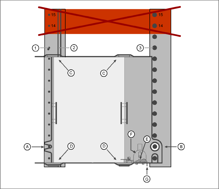
Fig. 6.2 - 18 Installation
(1) Centering pins
(2) Magnetic rail
(3) Centering ball
(14), (15) This position must not be filled.
The waffle-pack tray holder is placed on the component table as for a feeder module. There are
two different versions of the support, the only difference being the width.
Holder for large waffle tray (260x360mm², fills 9 locations)
item no. 00116430-01 and 6
Holder for small waffle tray (136x360mm², fills 5 locations)
item no. 00116432-01 6
6 Component handling User manual SIPLACE HF series
6.2 Technical data for the S feeder modules Software Version SR.50x.xx 01/2006 US Edition
268
PLEASE NOTE
– The waffle-pack tray holder can be set up at the following locations:
HF placement machine: locations 2 and 4
HF/3 placement machine: location 2
Feeder locations 14 and 15 on the component table
must not be filled
.
– The holder and the nozzle changer cannot be used at the same time at location 4.
– The component trolley cannot be docked in/out while the holder is fitted.
6.2.18.1 Assembly
Æ Insert the front side of the waffle-pack tray holder into the associated centering pin (A in Fig.
6.2 - 18
).
Æ Then position the hole on the rear side of the waffle-pack tray holder onto the centering ball
on the component feeder table (B in Fig. 6.2 - 18
).
Æ Make sure the waffle-pack tray is resting securely on the component feeder table.
Æ Position one side of the waffle-pack tray carrier in the mounting (C in Fig. 6.2 - 18). Then press
the other side into the mounting (D in Fig. 6.2 - 18
).
Æ Slide the waffle-pack tray up against the stop (E in Fig. 6.2 - 18).
Æ Secure the waffle-pack tray carrier by pressing the thrust pad (F in Fig. 6.2 - 18) downwards.
Æ To remove the waffle-pack tray carrier, press the thrust pad once more.
PLEASE NOTE
Using the holder for small waffle-pack trays (136mm) a waffle-pack tray (JEDEC or CENELEC
waffle-pack tray) can be fitted directly to the holder, in other words, without a waffle-pack tray car-
rier being used. However, the thrust pad will require changing.
WARNING
All locations must be equipped with feeder modules in order to guarantee operational reliability.
If there are not enough feeder modules available, unassigned locations should be fitted with a
hand guard (dummy feeder module). When a waffle-pack tray holder is set up, the remaining
locations have to be protected again with a hand guard.
User manual SIPLACE HF series 6 Component handling
Software Version SR.50x.xx 01/2006 US Edition 6.2 Technical data for the S feeder modules
269
6.2.18.2 Changing the retainer
Æ Hold the retainer (G in Fig. 6.2 - 18) firmly. Press the thrust pad downwards (F in Fig. 6.2 - 18)
and remove the retainer by pressing it out sideways.
6.2.18.3 Data entry
Define the waffle-pack trays as described in the SIPLACE Pro operating instructions.
6.2.19 Dip module
6
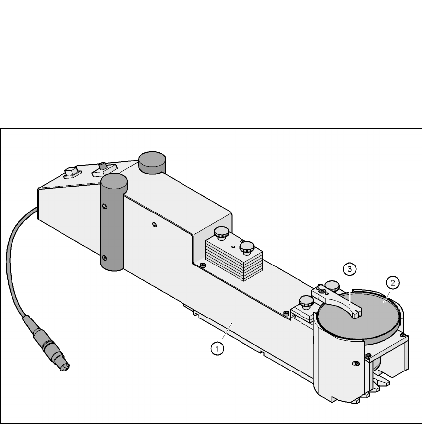
Fig. 6.2 - 19 Dip module
(1) Dip module
(2) Rotating plate
(3) Squeegee
6.2.19.1 Principle of dip fluxing
The dip module (item 1) is used to wet flip-chip and CSP components with flux or conductive ad-
hesive. The flux holder is a rotating plate (item 2) on which a thin film of flux (e.g. 40 µm) is created
with a squeegee (item 3). This method is particularly suitable for highly viscous (honey-like) fluxes.