00193922-03.pdf - 第127页
User manual SIPLAC E HF series 3 Technical data Software Vers ion SR.50x.xx 01/2006 US Edition 3.7 Placement heads 127 3.7.3.3 T echnical dat a 3 3 *) Please note that the component range that can be placed is also affec…
3 Technical data User manual SIPLACE HF series
3.7 Placement heads Software Version SR.50x.xx 01/2006 US Edition
126
Æ The 6-segment Collect&Place head has three axes - the DR or star axis, the Z axis and the
DP axis.
Æ The star rotates about the star axis with its 6 segments. The segments hold the sleeves.
There is a nozzle seated on every sleeve, which sucks up the components, and transports
them from the pick-up/placement position (1) to the reject position (2), to the optical centering
position (4) or to the turning position (5).
Æ The Z axis performs a vertical movement. Every sleeve that is in the bottom star position (1)
is raised or lowered by this axis, thus picking up the components from the feeder modules
and setting them down on the PCB. The Z axis is an "intelligent axis". It "notes" the pick-up
height of each conveyor track and the placement height for each component. This can speed
up the placement process. The programmed placement force remains constant.
Æ The DP axis rotates the optically centered component to the desired placement angle. The
sequences of movements of the rotation and translation axes are controlled by control cir-
cuits. Position and speed sensors send the actual values for the axis movement to the axis
control. The setpoint and actual values are compared and used to determine the force and
speed parameters for the servo amplifier, and thus the axis movement to be performed. The
vacuum values at the nozzle are constantly checked throughout the entire pick-up and place-
ment process in order to keep the placement error rate as low as possible.
User manual SIPLACE HF series 3 Technical data
Software Version SR.50x.xx 01/2006 US Edition 3.7 Placement heads
127
3.7.3.3 Technical data
3
3
*) Please note that the component range that can be placed is also affected by the pad geometry, the customer-specific
standards and the packaging tolerances.
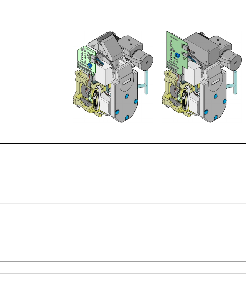
6-segment Collect&Place head
with standard component camera
(39x39)
6-segment Collect&Place head
with DCA camera
Component range *) 0603 to 32 x 32 mm² 0201 to flip-chip, bare die
Component specification
max. height
min. lead pitch
min. ball pitch
min. ball diameter
min. dimensions
max. dimensions
max. weight
8.5 mm
0.5 mm
0.56 mm
0.32 mm
1.6 x 0.8 mm²
32 x 32 mm²
5 g
8.5 mm
0.4 mm
0.2 mm
0.11 mm
0.6 x 0.3 mm²
13 x 13 mm²
5 g
Programmed power stage
1
2
3
4
5
Programmed set-down force [N]
2.4 ± 0.5
2.4 ± 0.5
3 + 1
4 + 1
5 + 1
Nozzle types 8 xx, 9 xx 8 xx, 9 xx
X/Y accuracy ± 45 µm/3 σ, ± 60 µm/4 σ ± 41 µm/3 σ, ± 55 µm/4 σ
Angular accuracy ± 0.2°/3 σ, ± 0.3°/4 σ ± 0.2°/3 σ, ± 0.3°/4 σ
3 Technical data User manual SIPLACE HF series
3.7 Placement heads Software Version SR.50x.xx 01/2006 US Edition
128
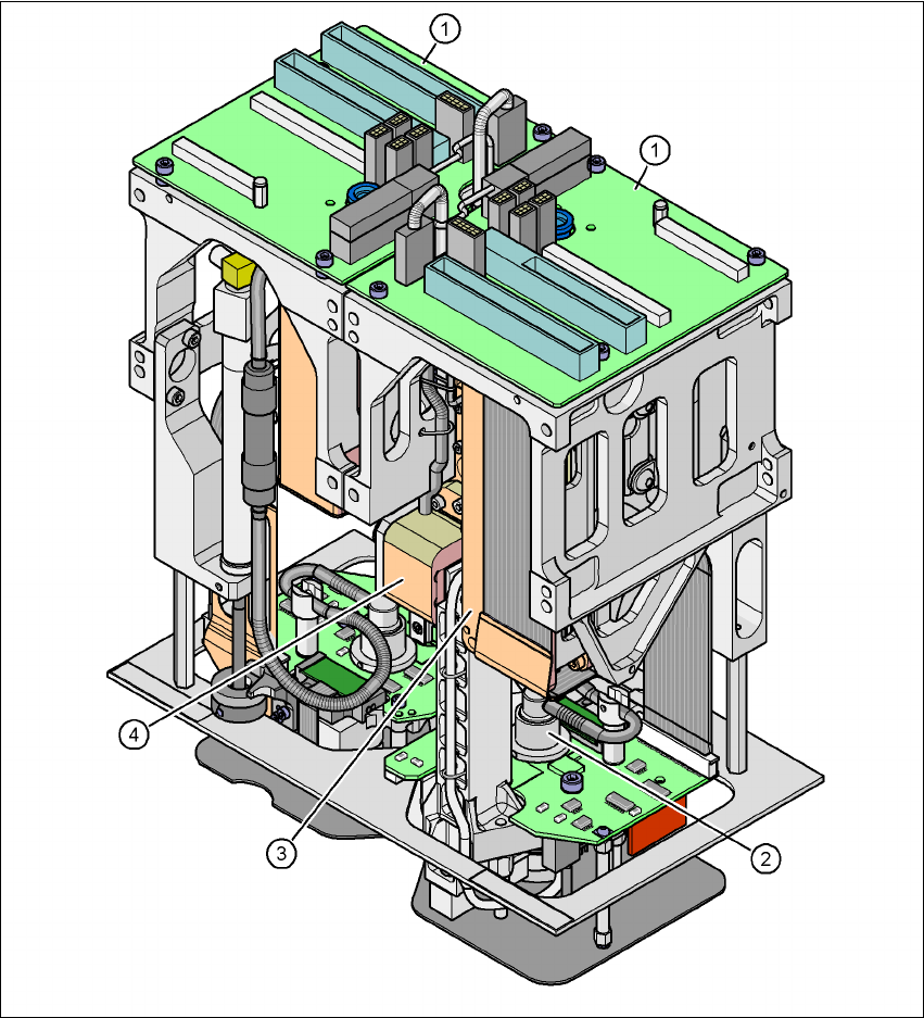
3.7.4 SIPLACE TwinHead for high-precision IC placement
3
Fig. 3.7 - 9 TwinHead for high-precision IC placement
3
(1) Pick&Place module - the TwinHead consists of 2 Pick&Place modules
(2) DP axis
(3) Z axis drive
(4) Incremental distance measuring system for the Z axis