00193922-03.pdf - 第119页
User manual SIPLAC E HF series 3 Technical data Software Vers ion SR.50x.xx 01/2006 US Edition 3.7 Placement heads 119 3 Fig. 3.7 - 4 12-segment Collect&Place head - F unction groups, part 2 3 (1) In termedia te dist…
3 Technical data User manual SIPLACE HF series
3.7 Placement heads Software Version SR.50x.xx 01/2006 US Edition
118
3.7.2 12-segment Collect&Place head for high-speed placement
3
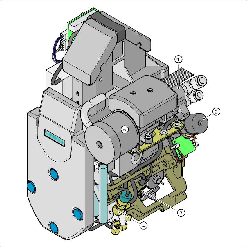
Fig. 3.7 - 3 12-segment Collect&Place head - Function groups, part 1
3
(1) Vacuum generator
(2) Turning station, DP axis
(3) Star with 12 sleeves, star axis
(4) Forced air valve
(5) Silencer
User manual SIPLACE HF series 3 Technical data
Software Version SR.50x.xx 01/2006 US Edition 3.7 Placement heads
119
3
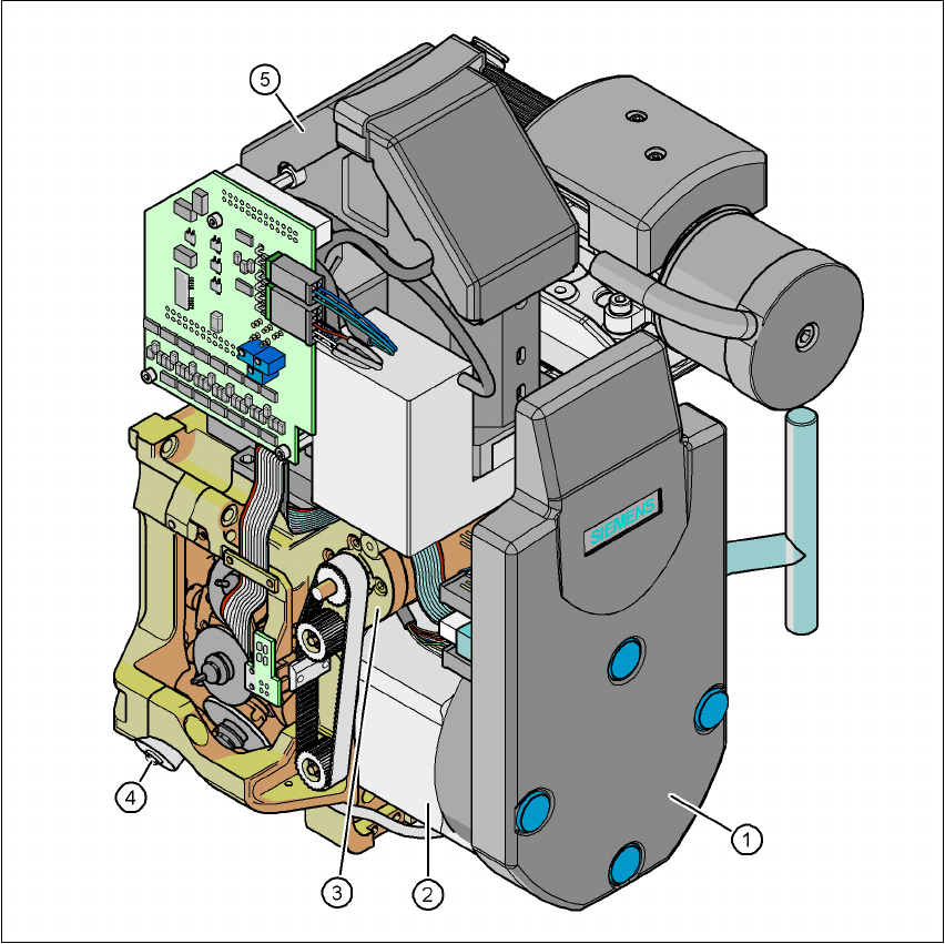
Fig. 3.7 - 4 12-segment Collect&Place head - Function groups, part 2
3
(1) Intermediate distributor board (beneath the cover)
(2) Star drive - DR motor
(3) Z axis motor
(4) Valve adjustment drive
(5) 24 x 24 component vision camera
3
3.7.2.1 Description
The 12-segment Collect&Place head works on the Collect&Place principle. This means that,
within each cycle, twelve components are picked up by the placement head, are optically cen-
tered on the way to the placement position and are rotated into the required placement angle.

3 Technical data User manual SIPLACE HF series
3.7 Placement heads Software Version SR.50x.xx 01/2006 US Edition
120
They are then set down gently and accurately on the PCB with a blast of air. The twelve nozzles
on SIPLACE Collect&Place heads turn about a horizontal axis, in contrast to conventional chip
shooters. This does not simply save space: the small diameter means that substantially smaller
centrifugal forces occur in comparison to conventional chip shooters. This largely eliminates the
risk of components slipping during transportation. 3
And there is yet another benefit: the cycle time of the Collect&Place head is the same for all com-
ponents, which means that the placement rate is not dependent on the component size. 3
Checking and self-learning functions 3
The reliability of the Collect&Place head is increased by various checking and self-learning func-
tions. 3
– For example, vacuum checks at the nozzles indicate whether the component was picked up
or set down correctly.
– A mark on the feeder is used to determine the precise component pick-up position on the
feeder.
– A camera on the placement head determines the precise angle of each component on the
nozzle. Any deviations from the required pick-up position are corrected before placement
takes place. When further components are picked up, the average of the deviations for the
last 10 placement operations are taken into account, thus further increasing pick-up accuracy.
– The package form is also checked, and the component is not placed if the geometric data thus
determined differs from the programmed data.
– The vertical axis (Z axis) for picking up and placing the component works in sensor stop
mode, in which differences in height during pick-up and any unevenness of the PCB surface
are compensated during placement. The average of the deviations during the last 10 place-
ment operations is also taken into account when adapting the further stroke and placement
speeds. The programmed placement force always remains constant.
– A component sensor may be installed on the C&P head in order to increase placement reli-
ability. The component sensor checks the edge ratio of the components, in addition to
whether the component is present at the nozzle. In this way it is possible to determine
whether the component was picked up by the nozzle transversely or on edge.
– The 12-segment Collect&Place head can optically center and place components from 0.6 x
0.3 mm² to 13 x 13 mm² using the optional DCA vision module. The DCA vision module opti-
mizes the speed and accuracy when placing high-speed flip-chips and bare die components
The values are shown in the table on page 122
.
3.7.2.2 Description of the functions
The 12-segment Collect&Place head has three axes - the DR or star axis, the Z axis and the DP
axis. 3