00193922-03.pdf - 第224页
4 Setting up and commissioning User manual SIPLACE HF series 4.5 Adapting the com ponent trolley to the PCB transport height Software Vers ion SR.50x.xx 01/2006 US Edition 224 Æ Unscrew the eye-bo lt from th e compone nt…
User manual SIPLACE HF series 4 Setting up and commissioning
Software Version SR.50x.xx 01/2006 US Edition 4.5 Adapting the component trolley to the PCB transport height
223
4.5.1 Warning instructions
WARNING
Only Siemens engineers or qualified personnel are permitted to adjust the component trolley
height.
Æ Always follow the applicable accident prevention regulations.
Æ Remove all the feeder modules from the component table bed if you want to adjust the height
of the component feeder table.
4.5.2 Tools and equipment
You will need the following tools and equipment to adjust the height of the component trolley:
– Hammer
– Punch, 8 mm
– Eye-bolt with M12 thread for raising the component trolley table
– Lifting device for raising the component trolley table, carrying capacity at least 80 kg
4.5.3 Changing the component trolley height
WARNING
Remove all the feeder modules from the component trolley table bed.
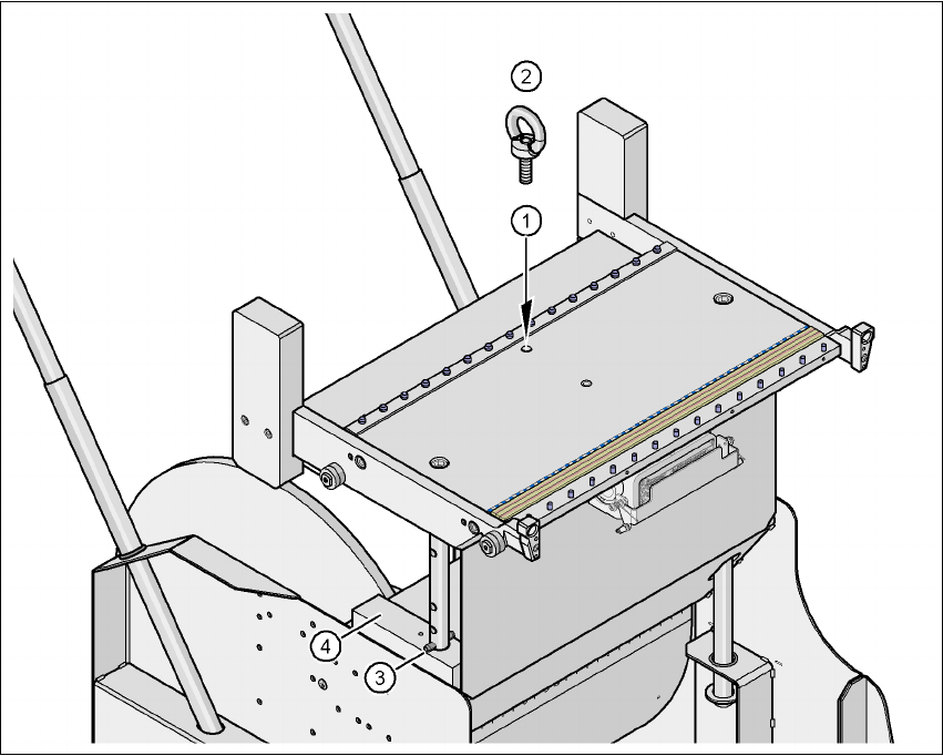
Æ Screw the eye-bolt into the M12 hole (item 1 in Fig. 4.5 - 2) in the component trolley table bed.
Æ Attach the hooks of the lifting device to the eye-bolt (item 2 in Fig. 4.5 - 2).
Æ Raise the component trolley bed slightly to expose the split pins (item 3 in Fig. 4.5 - 2).
Æ Use the punch to carefully tap out the spiral pins on both sides.
Æ Insert the spiral clamping pins into the holes for the required PCB conveyor height (item 3 in
Fig. 4.5 - 2
).
Æ Lower the component trolley bed slowly until the split pins lie on the supporting blocks (item 4
in Fig. 4.5 - 2
).
4 Setting up and commissioning User manual SIPLACE HF series
4.5 Adapting the component trolley to the PCB transport height Software Version SR.50x.xx 01/2006 US Edition
224
Æ Unscrew the eye-bolt from the component trolley table.
4
Fig. 4.5 - 2 Positions of the eye-bolt and flange bolts
(1) M12 hole for eye-bolt
(2) Eye-bolt, DIN 580 M12-St
(3) Spiral clamping pin, DIN 7343, 8x40 - St, 2x
(4) Supporting block, 2x

User manual SIPLACE HF series 5 Tasks on the machine
Software Version SR.50x.xx 01/2006 US Edition 5.1 Personnel profile
225
5 Tasks on the machine
This chapter contains a number of subjects that are intended to help you during your daily work
on a SIPLACE line.
For example, you are provided with preventative measures that you can take to minimize the down
time on the machine to obtain the highest possible level of efficiency for the SIPLACE line during
production.
In addition, the tasks of the operator and of the line engineer are described in an operator and line
engineer profile, respectively, in this chapter.
5.1 Personnel profile
5.1.1 Operator
5.1.1.1 Tasks of the operator
The operators should generally have attended the SIPLACE operation training course or have
been instructed by trained personnel.
The operating personnel are to be assigned the following tasks:
– Checking the assignment of components to the feeders
→ In addition, a set-up check is to be carried out several times a day, preferably at the start
of a shift, to make sure that the correct components are set up.
– Supplying the feeder modules with sufficient components
– Promptly refilling the components and splicing the tapes
– Checking to make sure that the components are in their correct pick-up positions (see Fig.
5.6 - 1
)
– Checking the flow of material to the PCBs on the input and output conveyor
– Checking the set-up quality
– Random sampling of the PCBs before they enter the soldering furnace.
– Observing the ESD regulations
– Preventing errors (see Section 5.6
, page 237)
– Observing the fault displays and messages at the station and passing the information on to
the line engineer if necessary
– Carrying out the preventive maintenance work specified in the Preventive Maintenance Man-
ual