00193922-03.pdf - 第140页
3 Technical data User manual SIPLACE HF series 3.10 Gantries Software Vers ion SR.50x.xx 01/2006 US Edition 140 3.10.3 Struc ture of the X ax is 3 Fig. 3.10 - 3 Structure of the X axis (1) Gantry arm (2) Head m ount (3) …
User manual SIPLACE HF series 3 Technical data
Software Version SR.50x.xx 01/2006 US Edition 3.10 Gantries
139
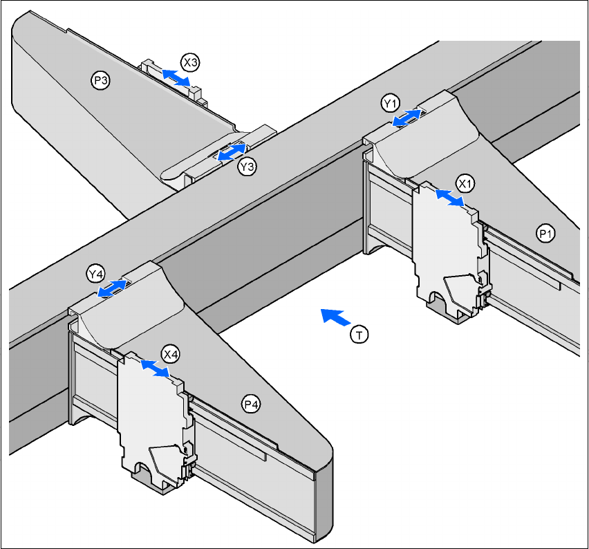
3.10.2 Position of the gantries for the HF/3 placement machine
3
Fig. 3.10 - 2 Position of the gantries for the HF/3 placement machine
3
P1 Gantry 1 3
X1 X axis, gantry 1 3
Y1 Y axis, gantry 1 3
P3 Gantry 3 3
X3 X axis, gantry 3 3
Y3 Y axis, gantry 3 3
P4 Gantry 4 3
X4 X axis, gantry 4 3
Y4 Y axis, gantry 4 3
(T) Direction of PCB transport
Placement area 2
Placement area 1
3 Technical data User manual SIPLACE HF series
3.10 Gantries Software Version SR.50x.xx 01/2006 US Edition
140
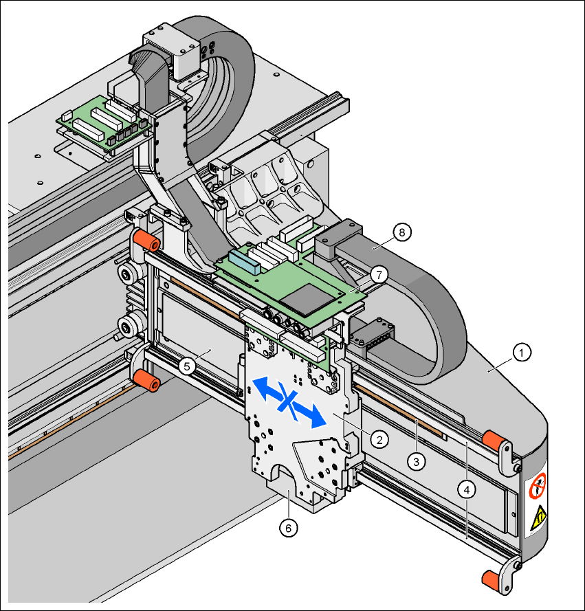
3.10.3 Structure of the X axis
3
Fig. 3.10 - 3 Structure of the X axis
(1) Gantry arm
(2) Head mount
(3) Linear distance measuring system
(4) Guide system
(5) Linear drive with permanent magnet
(6) Sub-gantry camera
(7) Head boards
(8) Cable and hose carrier

User manual SIPLACE HF series 3 Technical data
Software Version SR.50x.xx 01/2006 US Edition 3.10 Gantries
141
The X axis essentially consists of the following main modules: 3
– Gantry arm (1)
– Head mount (2)
– Linear distance measuring system (3)
– Guide system (4)
– Linear drive with permanent magnet (5)
– Cable and hose carrier (8)
The head mount (2) holds the following components: 3
– Sub-gantry camera (PCB camera for the PCB vision module) (6)
– Set of head boards (7)
– Measuring head for the measuring system
– Collect&Place head or SIPLACE TwinHead
The gantry arm (item 1 in Fig. 3.10 - 3
) is produced from a carbon fiber composite material which
makes the modules extremely light while, at the same time, being very rigid. 3
The X axis is driven by a linear motor. The secondary part of the drive consists of a permanent
magnet and is mounted on the gantry arm. The primary part is bolted to the head mount. The
head mount was designed to take all types of placement head - another indicator of the high level
of flexibility that can be achieved with SIPLACE placement machines. 3
3.10.4 Technical data for the X axis
3
Drive Direct, linear motor
Maximum speed 2.5 m/sec.
Traversing path 480 mm
Distance measuring system Metal linear scale
Scale length 520 mm
Resolution 1 µm