00193922-03.pdf - 第247页
User manual SIPLAC E HF series 6 Component handling Software Vers ion SR.50x.xx 01/2006 US Edition 6.1 Feeder modules 247 6 Component handling 6.1 Feeder modules The foll owing feed er modul es are curr ently av ailable …

5 Tasks on the machine User manual SIPLACE HF series
5.9 Note operating status indicator lamp Software Version SR.50x.xx 01/2006 US Edition
246
unchanged flashes (7, 7) unchanged Go to refill position
unchanged flashes (7, 7) unchanged Transport being initialized
unchanged flashes (7, 7) unchanged Place PCB in input conveyor
flashes (1, 10) flashes (7, 7) unchanged Remove PCB from output conveyor
unchanged flashes (7, 7) flashes (1, 10) Remove PCB from output conveyor 2
flashes (1, 10) flashes (7, 7) flashes (1, 10) Width adjustment
unchanged flashes (1, 10) unchanged Transport PCB
flashes (1, 10) flashes (7, 7) flashes (1, 10) Both output conveyors are cleared
on flashes (1, 10) on Transport error
on off on Go to service position
on Placement
flashes (1, 20) Waiting for processing data
Error display
on off unchanged Machine error, right
on off unchanged Track empty, right
on off unchanged Nozzle configuration, right
on off unchanged Transport error, right
on off on Fiducial error, left and right
on off on Fiducial error, left and right
unchanged off on Track empty, left
unchanged off on Nozzle configuration, left
unchanged off on Transport error, left
unchanged off on Machine error, left
Pick-up error display
unchanged unchanged flashes (1, 20)
First track empty, left
unchanged unchanged flashes (5, 20)
Further tracks empty, left
unchanged unchanged flashes (5, 5)
Penultimate track in use
unchanged unchanged flashes (1, 2)
Last track in use, right
flashes (1, 20) unchanged unchanged
First track empty, right
flashes (5, 20) unchanged unchanged
Further tracks empty, right
flashes (5, 5) unchanged unchanged
Penultimate track in use, right
flashes (1, 2) unchanged unchanged
Last track in use, right
L1 (white)
(right lamp)
L2 (green) L3 (white)
(left lamp)
Meaning

User manual SIPLACE HF series 6 Component handling
Software Version SR.50x.xx 01/2006 US Edition 6.1 Feeder modules
247
6 Component handling
6.1 Feeder modules
The following feeder modules are currently available to provide the placement machine with the
various component types:
Tape feeder modules 6
– 8 mm SII feeder module
– 3 x 8 mm S feeder module, 3 x 8 mm S feeder module for 0201/0402 components
– 12 mm S feeder module for powdered metal-based capacitors, C/D model
– 12 mm S feeder module for powdered metal-based capacitors, E model
– S feeder module for 12/16 mm, 24/32 mm, 44 mm, 56 mm, 72 mm and 88 mm
– S DP feeder module for deep pockets, 24/32 mm, 44 mm and 56 mm
Other feeder modules 6
– Linear vibratory feeder, type 3
– Bulk case feeder module
– Surf tape feeder module for 8 mm, 12 mm, 16 mm and 24 mm
These feeder modules can be used to process all components with the most common package
forms, such as bulk cases, stick magazines and taped components.
The most important feature of the modular component feeding system is its great flexibility. For
example, the feeding rate can be set on the feeder module. Paper and blister tapes can be pro-
cessed with the tape feeder modules. In this way, just a small selection of feeder modules is suf-
ficient for inserting a wide range of component types.
The position detection system on the feeder modules can precisely determine the component
pick-up position. The position detection is carried out automatically whenever the feeder module
or component trolley is changed.
The feeder modules can be quickly and easily changed or replaced, even by unskilled personnel.
PLEASE NOTE
Detailed information on the feeder modules can be found in the operating instructions for compo-
nent feeder modules.
6 Component handling User manual SIPLACE HF series
6.1 Feeder modules Software Version SR.50x.xx 01/2006 US Edition
248
6.1.1 Safety instructions for processing capacitors based on powdered metal
There is a risk associated with processing capacitors based on powdered metal (e.g. tantalum).
The risk is that
– an exothermic reaction, i.e. a sudden build-up of heat, may occur, if these components are
damaged. If the ambient conditions are unfavorable, and depending on the capacitance, this
build-up of heat can cause damage.
– This effect can occur when these components are cut.
Please contact your suppliers to clarify whether the components that you handle are affected.
In extremely rare cases, this risk can occur in the tape cutter of SIPLACE machines, with the re-
mote possibility of causing a smoldering fire in the waste tape.
The ambient conditions are unfavorable if:
(1) The components remain on the tape while the set tape cycle is checked (since the operator
can cycle the feeder module onward without removing components during this check).
(2) The components remain on the tape, e.g. due to a tear in the cover foil.
(3) The components remain on the tape, and the components or tape do not conform to the spec-
ification, thus increasing the pick-up error rate.
Please follow the instructions given below to minimize the risk when placing capacitors based on
powdered metal.
(1) If the component tape is cycled onward manually, the operator must remove any components
remaining in the tape pocket.
(2) If the cover foil tears, the operator must remove any components remaining on the tape.
(3) The waste tape container must be emptied regularly (recommended interval: every hour)
6
WARNING
To avoid the risk, it is essential to use only feeder modules
that have been approved for placing such components,
namely:
for model C/D item no.: 00141118-01
for model E item no.: 00141117-01
6
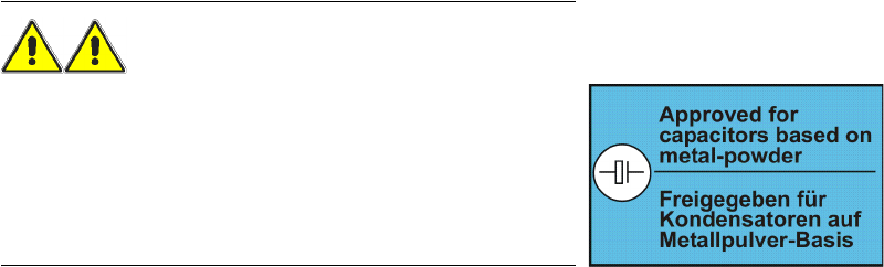
The feeder modules are labeled
as shown below:
6