00193922-03.pdf - 第282页
6 Component handling User ma nual SIPLACE HF series 6.4 Used tape c hute, SIPLACE H F Software Vers ion SR.50x.xx 01/2006 US E dition 282 6.4 Used t ape chute, SIPLACE HF 6 Fig. 6.4 - 1 Used tape c hute for SIPLACE HF Th…
User manual SIPLACE HF series 6 Component handling
Software Version SR.50x.xx 01/2006 US Edition 6.3 Component trolley
281
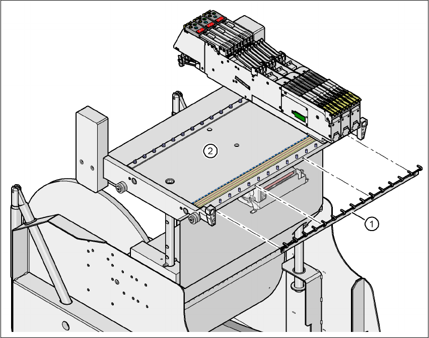
6.3.8 Feeder module fixing
The feeder module fixing is an additional mechanical locking device. It prevents the feeder mod-
ules accidentally moving on the component table and thus prevents the risk of collision with the
placement head.
The feeder module fixing is fixed to the front panel of the component table using screws. The claws
fix the feeder module feet. One feeder module fixing is needed for each component trolley.
6
Fig. 6.3 - 8 Feeder module fixing
6
(1) Feeder module fixing
(2) Component feeder table
6 Component handling User manual SIPLACE HF series
6.4 Used tape chute, SIPLACE HF Software Version SR.50x.xx 01/2006 US Edition
282
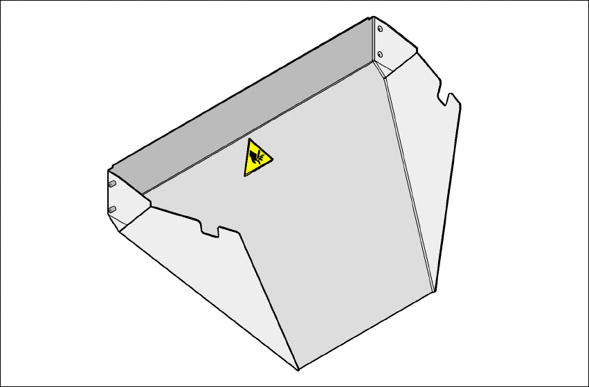
6.4 Used tape chute, SIPLACE HF
6
Fig. 6.4 - 1 Used tape chute for SIPLACE HF
The used tape chute for the SIPLACE HF is attached to the component trolley docking unit. The
waste tape that is chopped up by the tape cutter slides onto the used tape chute and into the waste
container of the component trolley.
User manual SIPLACE HF series 6 Component handling
Software Version SR.50x.xx 01/2006 US Edition 6.5 Removing the used tape channel dividing plate
283
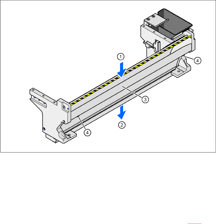
6.5 Removing the used tape channel dividing plate
In the standard version, the used tape channel can guide component tapes with a maximum
pocket height of 17 mm to the pneumatic tape cutter.
6
Fig. 6.5 - 1 Used tape channel with component reject bin
(1) Inlet slot for the used tapes
(2) Outlet slot for the used tape above the pneumatic tape cutter
(3) Dividing plate for tapes < 17 mm (can be removed for tapes > 17 mm)
(4) DIN 84 - M3x6 screw, 2x
If feeder modules that process component tapes with a pocket height > 17 mm are used, such as,
for example, the 44 mm S DP feeder module, then the separating plate (item 3 in Fig. 6.5 - 1
) must
be removed.