00193922-03.pdf - 第266页
6 Component handling User ma nual SIPLACE HF series 6.2 Technical dat a for the S feeder modules S oftware Version S R.50x.xx 01/2006 US Edition 266 6.2.17.2 T echnical da ta 6 6 6 6.2.17.3 Parameters f or surf t ape fee…
User manual SIPLACE HF series 6 Component handling
Software Version SR.50x.xx 01/2006 US Edition 6.2 Technical data for the S feeder modules
265
6.2.17 Surf tape feeder module
6.2.17.1 Overview
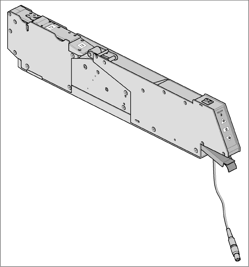
For placing bare dies, you will need the surf tape feeder module for feeding components. There
are versions of these feeder modules for 8-, 12- or 16 mm tapes.
6
Fig. 6.2 - 17 Surf tape feeder module
The surf tape feeder module can be ordered from Hover-Davis (www.hoverdavis.com).
Handling of the feeder module is described in the operating instructions for feeder modules.

6 Component handling User manual SIPLACE HF series
6.2 Technical data for the S feeder modules Software Version SR.50x.xx 01/2006 US Edition
266
6.2.17.2 Technical data
6
6
6
6.2.17.3 Parameters for surf tape feeder modules
The parameters for the surf tape feeder module can be modified on the SIPLACE Pro computer.
Tape widths 8/12/16 mm
Recommended tape and component
sizes
8 mm: for 1 x 1 mm² - 2.3 x 2.3 mm² components
12 mm: for 2.3 x 2.3 mm² - 5 x 5 mm² components
16 mm: for 3.8 x 3.8 mm² - 9.5 x 9.5 mm² components
Packaging accuracy of the bare die on
the surf tape
Bare die size up to 2.3 x 2.3 mm²: +/- 100 µm, 6 σ
Bare die size over 2.3 x 2.3 mm²: +/- 200 µm, 6 σ
(related to the center of the pocket)
Required distance between the edges
of the bare dies to the tape pocket Min. 0.4 mm
Pusher needle Single or triple needle depending on the die size
Tape material Metric
Tape standard IEC 286-3, DIN-IEC-286, EIA 481, and JIS C 0806
Tape reel diameter 7" to 15"
Footprint of the feeder module 1 location on the component table
User manual SIPLACE HF series 6 Component handling
Software Version SR.50x.xx 01/2006 US Edition 6.2 Technical data for the S feeder modules
267
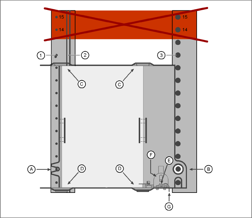
6.2.18 Waffle-pack tray holder
The waffle-pack tray holder allows components to be picked up from individual waffle-pack trays.
The waffle-pack trays are changed manually.
6
Fig. 6.2 - 18 Installation
(1) Centering pins
(2) Magnetic rail
(3) Centering ball
(14), (15) This position must not be filled.
The waffle-pack tray holder is placed on the component table as for a feeder module. There are
two different versions of the support, the only difference being the width.
Holder for large waffle tray (260x360mm², fills 9 locations)
item no. 00116430-01 and 6
Holder for small waffle tray (136x360mm², fills 5 locations)
item no. 00116432-01 6