00193922-03.pdf - 第330页
7 Station extensions User manual SIPLA CE HF series 7.5 PCB barcode scanner Software Vers ion SR.50x.xx 01/2006 US Edition 330 7.5.7.5 Pos itioning a long the wid th of t he PCB - Scanning beam along the direction of tr …
User manual SIPLACE HF series 7 Station extensions
Software Version SR.50x.xx 01/2006 US Edition 7.5 PCB barcode scanner
329
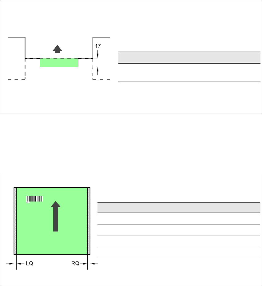
7.5.7.3 PCB overshoot over the machine with the dual conveyor
7
Fig. 7.5 - 6 PCB overshoot over the machine with the dual conveyor
7.5.7.4 Positioning along the width of the PCB -
Scanning beam
across
the direction of travel
7
Fig. 7.5 - 7 Positioning along the width of the PCB - Scanning beam across the direction of travel
PCB barcode scanner Overshoot [mm]
2D underside on the
dual conveyor
17
Input side of the downstream machine
Output side of the upstream machine
PCB barcode scanner LQ [mm] RQ [mm]
2D topside 3 3
1D topside 3 3
2D underside 5 5
1D underside 5 5
7 Station extensions User manual SIPLACE HF series
7.5 PCB barcode scanner Software Version SR.50x.xx 01/2006 US Edition
330
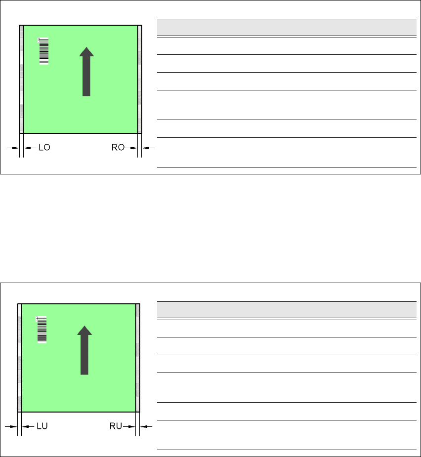
7.5.7.5 Positioning along the width of the PCB -
Scanning beam
along
the direction of travel,
PCB barcode scanner 1D
topside
7
Fig. 7.5 - 8 Positioning along the width of the PCB - Scanning beam along the direction of travel
PCB barcode scanner 1D topside
7
7.5.7.6 Positioning along the width of the PCB -
Scanning beam
along
the direction of travel,
PCB barcode scanner 1D
underside
7
Fig. 7.5 - 9 Positioning along the width of the PCB - Scanning beam along the direction of travel
PCB barcode scanner 1D underside
SC Single conveyor
DC1 Dual conveyor, track 1
DC2 Dual conveyor, track 2
SM1 Dual conveyor in Single conveyor mode, track 1
SM2 Dual conveyor in Single conveyor mode, track 2
PCB dimensions/conveyor LO [mm] RO [mm]
460 mm / SC 3 20
508 mm / SC 3 44
216 mm / DC1 3 24
250 mm / DC1
450 mm / SM1
358
216 mm / DC2 3 3
250 mm / DC2
450 mm / SM2
33
PCB dimensions/conveyor LU [mm] RU [mm]
460 mm / SC 20 3
508 mm / SC 44 3
216 mm / DC1 3 3
250 mm / DC1
450 mm / SM1
33
216 mm / DC2 24 3
250 mm / DC2
450 mm / SM2
58 3
User manual SIPLACE HF series 7 Station extensions
Software Version SR.50x.xx 01/2006 US Edition 7.6 Multicolor PCB camera (type 18)
331
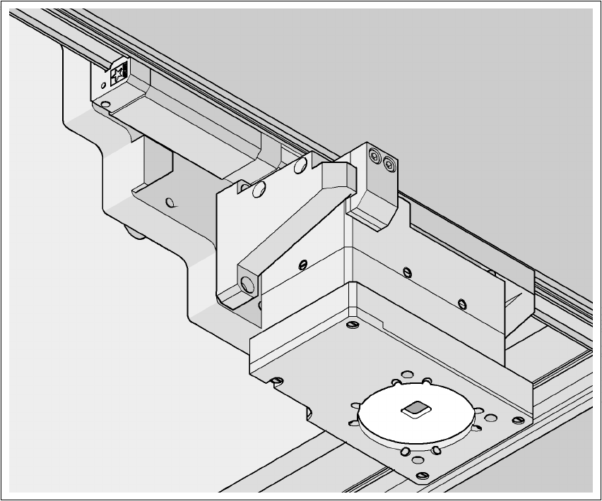
7.6 Multicolor PCB camera (type 18)
Item no. 00119674-xx Multicolor PCB vision module HF/3
Item no. 00119676-xx Multicolor PCB vision module HF
7.6.1 General
As an option, a multicolor PCB camera can be installed in place of the sub-gantry camera. The
multicolor PCB camera offers four different types of illumination. This greatly increases fiducial de-
tection and thus the centering accuracy.
7
Fig. 7.6 - 1 Multi-color PCB camera