00193922-03.pdf - 第348页
7 Station extensions User manual SIPLA CE HF series 7.12 Coplanarity laser module Software Vers ion SR.50x.xx 01/2006 US E dition 348 7 Fig. 7.12 - 5 Coplanarity module (1) Laser module (2) Connecting cab le (3) Red LED:…
User manual SIPLACE HF series 7 Station extensions
Software Version SR.50x.xx 01/2006 US Edition 7.12 Coplanarity laser module
347
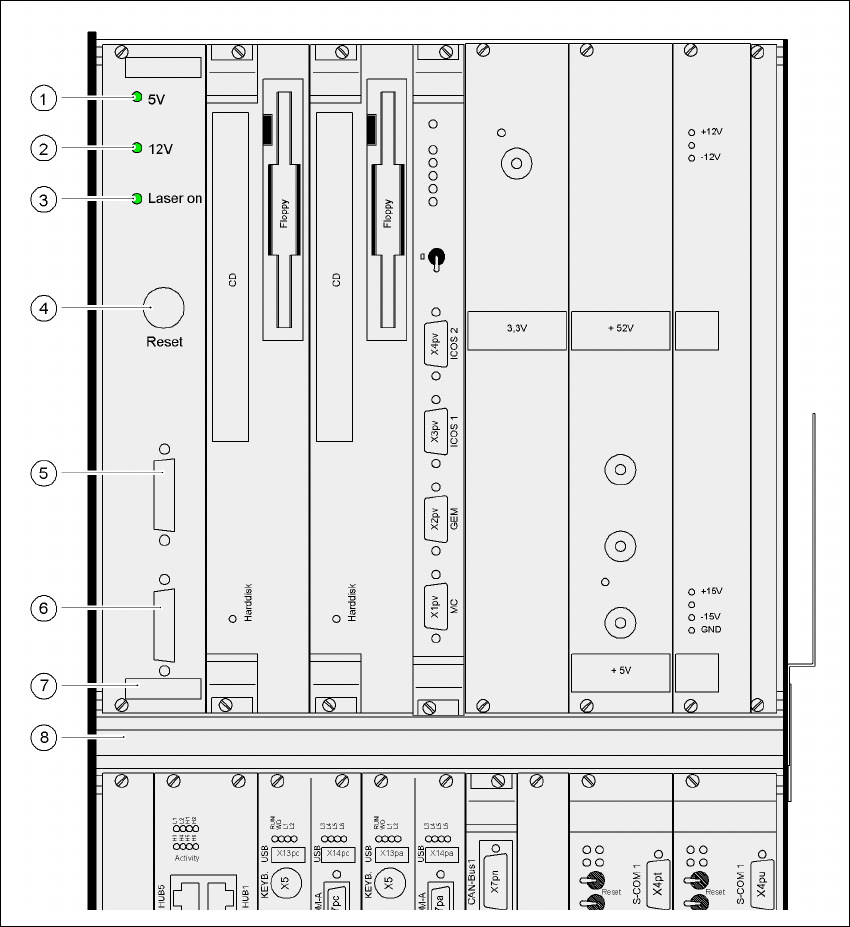
Fig. 7.12 - 4 Coplanarity laser module overview
(1) Green LED: 5V operating voltage
(2) Green LED: 12V operating voltage
(3) Green LED: laser module switched on
(4) RESET key
(5) SUB-D plug, 9-pin, COM2: to the machine controller
(6) SUB-D plug, 15-pin: to the laser module
(7) Analysis unit with control section
(8) Computer unit
7 Station extensions User manual SIPLACE HF series
7.12 Coplanarity laser module Software Version SR.50x.xx 01/2006 US Edition
348
7
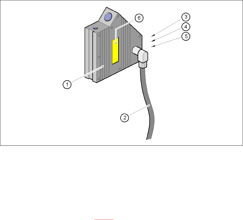
Fig. 7.12 - 5 Coplanarity module
(1) Laser module
(2) Connecting cable
(3) Red LED: OUT OF RANGE
(4) Red LED: POOR TARGET
(5) Green LED: LASER ON
(6) ’Laser class 3B’ sticker, see Fig. 7.12 - 2
User manual SIPLACE HF series 7 Station extensions
Software Version SR.50x.xx 01/2006 US Edition 7.13 SIPLACE productivity lift
349
7.13 SIPLACE productivity lift
7.13.1 Concept of parallel placement
Placement lines are generally arranged in series and are linked to one another serially. The place-
ment program is processed sequentially while the PCBs are transported from one machine to the
next. This means that the placement of a PCB is distributed between various machines.
7
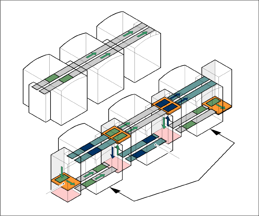
Fig. 7.13 - 1 A comparison of serial and parallel lines
When machines are connected in parallel, the components to be placed by individual machines
are combined. Several machines work through the same placement program. They place all the
components on one machine that would be distributed between several machines with serial pro-
cessing. When one machine runs out of capacity, the PCBs are moved to and placed at the next
machine with the same placement program. This combination of machines with the same compo-
nents to be placed is known as a group or “cluster”.
Serial line
Parallel line
Underfloor
conveyor
Group (cluster)
Horizontal/
vertical lift