00193922-03.pdf - 第131页
User manual SIPLAC E HF series 3 Technical data Software Vers ion SR.50x.xx 01/2006 US Edition 3.7 Placement heads 131 3.7.4.3 T echnical dat a 3 3 3 *) Please note that the component range that can be placed is also aff…
3 Technical data User manual SIPLACE HF series
3.7 Placement heads Software Version SR.50x.xx 01/2006 US Edition
130
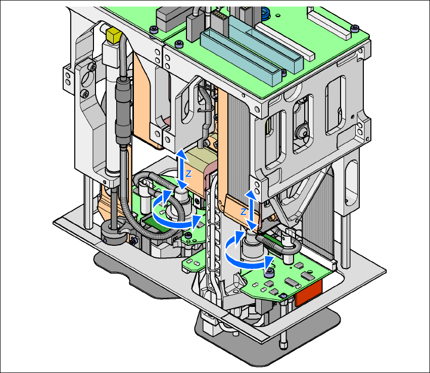
The DP axis rotates the optically centered component to the desired placement angle. The ro-
tation axis is driven by a stepping motor. The motor shaft is designed as a sleeve. At the top end
is the incremental disk for angle analysis, while the nozzle holding device is at the bottom end. 3
The sequences of movements of the rotation and translation axes are controlled by control cir-
cuits. Position and speed sensors send the actual values for the axis movement to the axis con-
trol. The setpoint and actual values are compared and used to determine the force and speed
parameters for the servo amplifier, and thus the axis movement to be performed. 3
The vacuum values at the nozzle are constantly checked throughout the entire pick-up and
placement process in order to keep the placement error rate as low as possible. 3
3
Fig. 3.7 - 10 Description of the functions
3
User manual SIPLACE HF series 3 Technical data
Software Version SR.50x.xx 01/2006 US Edition 3.7 Placement heads
131
3.7.4.3 Technical data
3
3
3
*) Please note that the component range that can be placed is also affected by the pad geometry, the customer-specific
standards and the packaging tolerances.
**) If standard nozzles are used
Optical centering with Stationary P&P component vision
camera (type 22) 50 x 40
Stationary P&P component vision
camera (type 20) 8 x 8
Component range *) 0603 to SO, PLCC, QFP, BGA, special
components, bare dies, flip-chips
0201 to SO, PLCC, QFP, sockets,
plugs, BGA, special components,
bare dies, flip-chips, shields
Component specification
max. height
min. lead pitch
min. ball pitch
min. ball diameter
min. dimensions
max. dimensions
max. weight
25 mm (higher available on request)
0.4 mm
0.56 mm
0.32 mm
1.6 x 0.8 mm²
50 x 40 mm² (single measurement)
For use with two nozzles:
50 x 50 mm² or
69 x 10 mm ²
For use with one nozzle:
85 x 85 mm² or
125 x 10 mm²
Up to 200 x 125 mm² (with restrictions)
100 g **)
25 mm (higher available on request)
0.25 mm
0.14 mm
0.08 mm
0.6 x 0.3 mm²
8 x 8 mm² (single measurement)
100 g **)
Programmable set-down
force
1.0 N - 15 N 1.0 N - 15 N
Nozzle types 5 xx (standard)
4 xx + adapter
8 xx + adapter
9 xx + adapter
5 xx (standard)
4 xx + adapter
8 xx + adapter
9 xx + adapter
Nozzle spacing on the two
Pick&Place heads
70.8 mm 70.8 mm
X/Y accuracy ± 26 µm / 3 σ, ± 35 µm / 4 σ ± 22 µm / 3 σ, ± 30 µm / 4 σ
Angular accuracy ± 0.05° / 3 σ, ± 0.07° / 4 σ ± 0.05° / 3 σ, ± 0.07° / 4 σ
3 Technical data User manual SIPLACE HF series
3.8 Electrical and pneumatic connection points Software Version SR.50x.xx 01/2006 US Edition
132
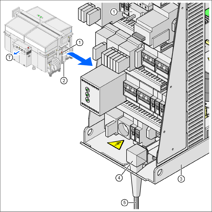
3.8 Electrical and pneumatic connection points
3.8.1 Electrical connection points
3
Fig. 3.8 - 1 Electrical connection points on the placement machine
3
(1) Main power switch
(2) Cover over the power supply unit
(3) Power supply unit
(4) Angle for the cable gland
(5) Power cable
(T) Direction of PCB transport