00193922-03.pdf - 第293页
User manual SIPLAC E HF series 7 Station extensions Software Vers ion SR.50x.xx 01/2006 US Edition 7.1 Nozzle changer 293 7.1.1.2 Position of the nozzl e changers for the C&P12 head on the HF/3 machine 1 or 2 nozzle …
7 Station extensions User manual SIPLACE HF series
7.1 Nozzle changer Software Version SR.50x.xx 01/2006 US Edition
292
WARNING 7
Only install the associated nozzle changer for each placement head. There is a risk of head
crashes with mixed configurations.
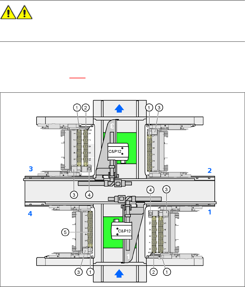
7.1.1.1 Position of the nozzle changers for the C&P12 head on the HF machine
1 or 2 nozzle changers may be installed at locations 1 and 3 for the 12 segment Collect&Place
head (items 1 and 2 in Fig. 7.1 - 2
). A nozzle changer may be installed at locations 2 and 4. This
gives a total capacity of 6 nozzle changers with 30 magazines and a total of 360 nozzle holders.
7
Fig. 7.1 - 2 Position of the nozzle changer for the 12-segment Collect&Place head on the HF machine
7
(1) Nozzle changer, "row 1"
(2) Nozzle changer, "row 2"
(3) Reject bin for components
(4) Take-off device and reject bin for nozzles
(5) Nozzle magazine
User manual SIPLACE HF series 7 Station extensions
Software Version SR.50x.xx 01/2006 US Edition 7.1 Nozzle changer
293
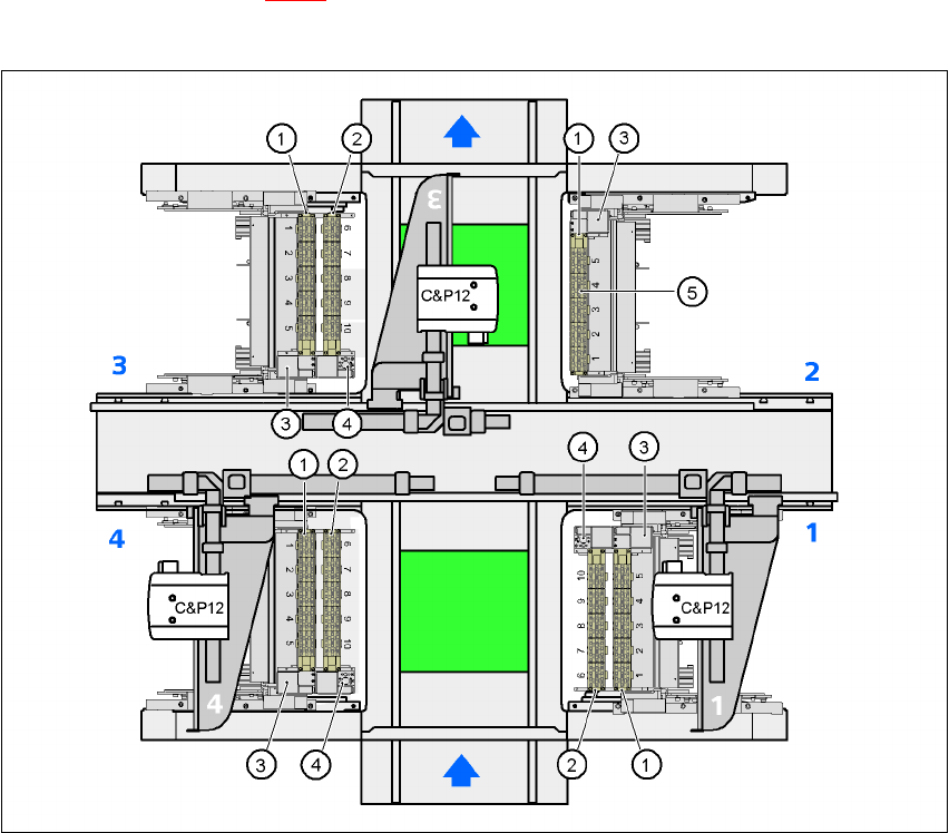
7.1.1.2 Position of the nozzle changers for the C&P12 head on the HF/3 machine
1 or 2 nozzle changers may be installed at locations 1, 3, and 4 for the 12 segment Collect&Place
head (items 1 and 2 in Fig. 7.1 - 3
). One nozzle changer may be installed at location 2. This gives
a total capacity of 7 nozzle changers with 35 magazines and a total of 420 nozzle holders.
7
Fig. 7.1 - 3 Position of the nozzle changer for the 12-segment Collect&Place head on the HF/3 machine
7
(1) Nozzle changer, "row 1"
(2) Nozzle changer, "row 2"
(3) Reject bin for components
(4) Take-off device and reject bin for nozzles
(5) Nozzle magazine
7 Station extensions User manual SIPLACE HF series
7.1 Nozzle changer Software Version SR.50x.xx 01/2006 US Edition
294
7.1.1.3 Technical data
7
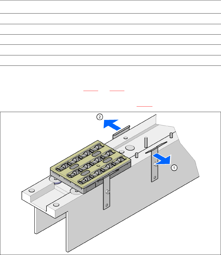
7.1.1.4 Assembly
"Row 1" nozzle changers (see Figs. 7.1 - 2 and 7.1 - 3) are each fixed to the component trolley
docking unit. There is an additional assembly kit for the "row 2" nozzle changer. This kit consists
of the take-off device and the nozzle reject bin (see section 7.1.1.9
).
7
Fig. 7.1 - 4 Assembly position
(1) Spring hook pointing toward the operator
(2) Retaining clamp pointing toward the PCB conveyor
Æ Align the nozzle changer so that the moving spring hooks always point toward the operator,
while the retaining clamps always point toward the PCB conveyor.
Nozzle changer for the 12-segment Collect&Place head
Dimensions (length x width x height) 449 x 62.7 x 77.7 mm³
Number of nozzle holders 60
Nozzle types 9 xx
Time required to open and close the locking plate < 200 ms
Compressed air connection 0.48 MPa (4.8 bar)