00193922-03.pdf - 第133页
User manual SIPLAC E HF series 3 Technical data Software Vers ion SR.50x.xx 01/2006 US Edition 3.8 Electrical and pneumatic connection p oints 133 3.8.2 Pneumatic connection point 3 Fig. 3.8 - 2 P neumatic connect ion po…
3 Technical data User manual SIPLACE HF series
3.8 Electrical and pneumatic connection points Software Version SR.50x.xx 01/2006 US Edition
132
3.8 Electrical and pneumatic connection points
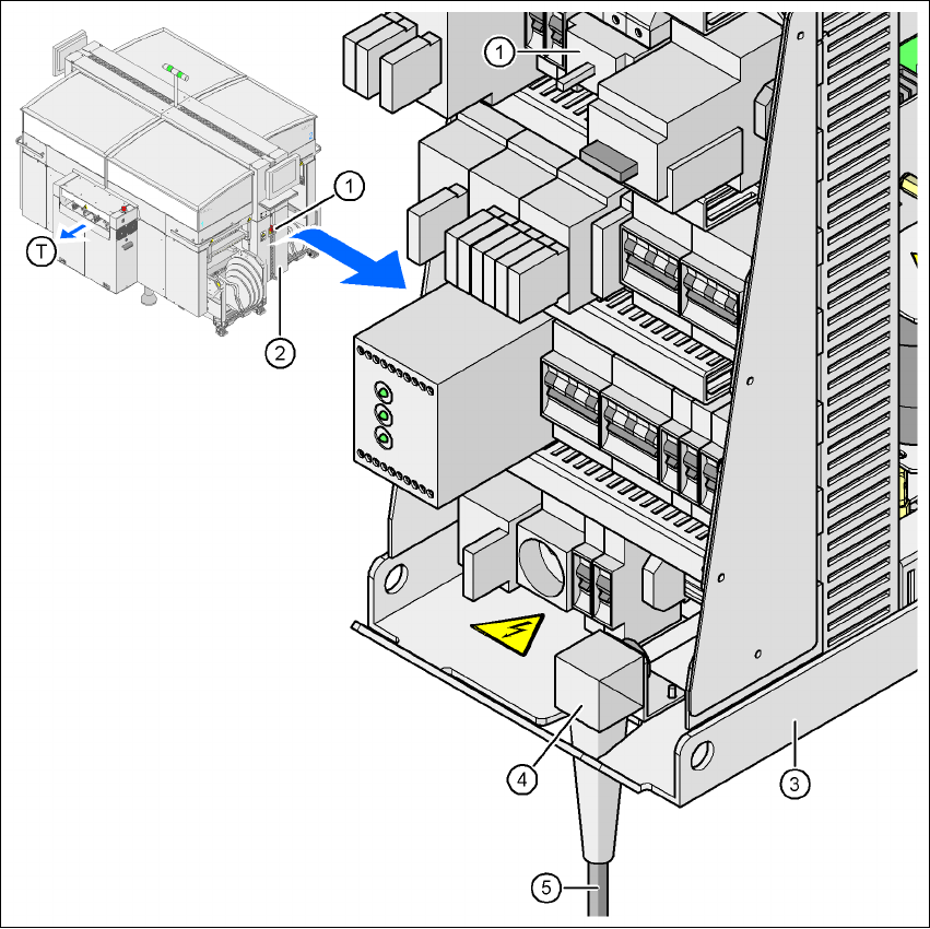
3.8.1 Electrical connection points
3
Fig. 3.8 - 1 Electrical connection points on the placement machine
3
(1) Main power switch
(2) Cover over the power supply unit
(3) Power supply unit
(4) Angle for the cable gland
(5) Power cable
(T) Direction of PCB transport
User manual SIPLACE HF series 3 Technical data
Software Version SR.50x.xx 01/2006 US Edition 3.8 Electrical and pneumatic connection points
133
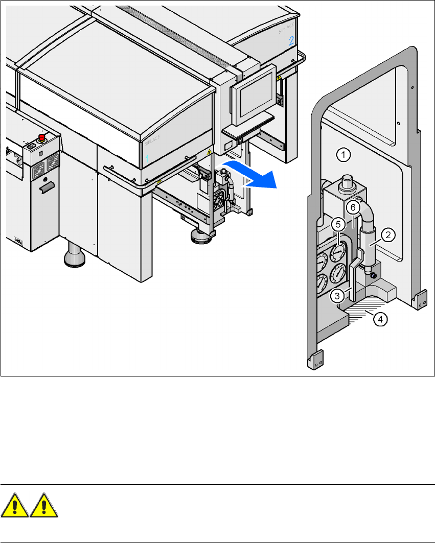
3.8.2 Pneumatic connection point
3
Fig. 3.8 - 2 Pneumatic connection point on the placement machine
3
(1) Pneumatic unit
(2) Coupling for connecting the compressed air hose
(3) Stop valve
(4) Recess for the air hose
WARNING
NEVER detach compressed air lines while they are still pressurized. Risk of injury. 3
3 Technical data User manual SIPLACE HF series
3.9 Controls Software Version SR.50x.xx 01/2006 US Edition
134
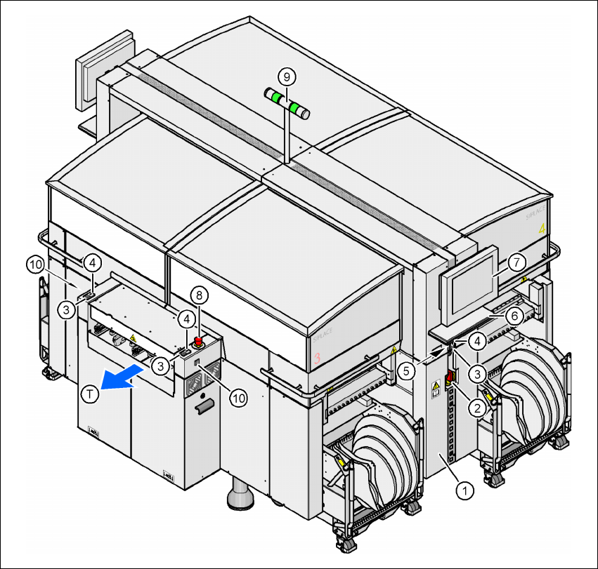
3.9 Controls
3.9.1 Controls and displays
3
Fig. 3.9 - 1 Controls and displays
(1) Operator panel on the power supply side (7) LCD touchscreen
(2) Main power switch (8) Emergency stop button
(3) Stop button (black) (9) Indicator lamp
(4) Start button (white) (10) Buttons for docking the component trolley
in and out
(5) Component counter
(6) Keyboard (T) Direction of PCB transport