00193922-03.pdf - 第274页
6 Component handling User ma nual SIPLACE HF series 6.3 Component trolley Software Vers ion SR.50x.xx 01/2006 US Edition 274 6.3.1 Structure of th e component trolley The com ponent tro lley esse ntially consis ts of the…
User manual SIPLACE HF series 6 Component handling
Software Version SR.50x.xx 01/2006 US Edition 6.3 Component trolley
273
imity switches signal whether the component trolley has been docked in correctly.
– The component trolley is fixed so precisely to the placement machine that it is even suitable
for processing 0201 components.
– The component trolley can be adjusted to PCB transport heights of 830 mm, 900 mm,
930 mm and 950 mm in just a few simple actions.
– The tape container can hold tape reels with a diameter of up to 15" (optional up to 19").
– Every component trolley has a unique identification number.
6 Component handling User manual SIPLACE HF series
6.3 Component trolley Software Version SR.50x.xx 01/2006 US Edition
274
6.3.1 Structure of the component trolley
The component trolley essentially consists of the chassis, the component table for holding the
feeder modules, the communication unit, tape reel container and the waste container.
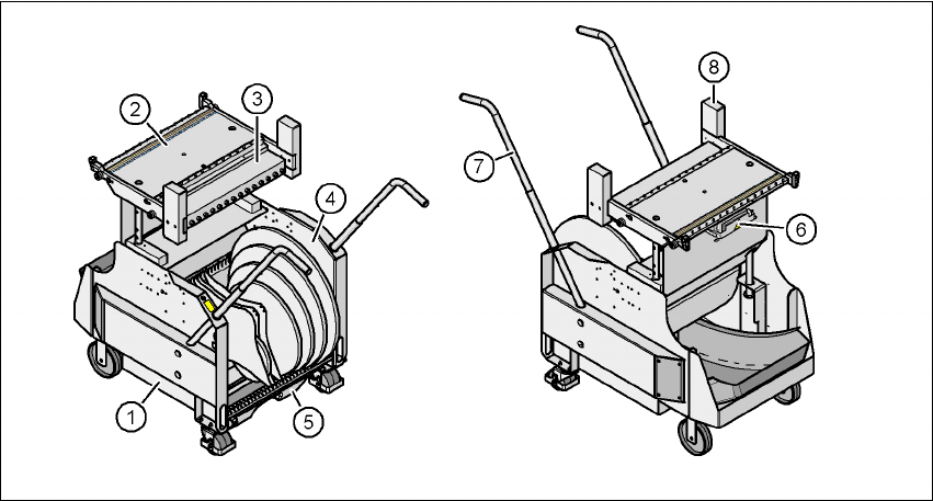
Fig. 6.3 - 3 Component trolley: front and back view
(1) Chassis
(2) Component feeder table
(3) Communication unit
(4) Tape reel container
(5) Waste tape container
(6) Interface for the main power supply, communication, the safety circuit and the compressed
air supply for the bulk case feeder module
(7) Handle
(8) Hand guard

User manual SIPLACE HF series 6 Component handling
Software Version SR.50x.xx 01/2006 US Edition 6.3 Component trolley
275
Description of the modules 6
The chassis (item 1) runs smoothly and is easy to maneuver.
The handles (item 7) can be folded up or down.
The component feeder table (item 2) has a capacity of up to 15 locations for 30 mm wide feeder
modules. The feeder modules are mechanically centered on the table using centering pins and
centering balls. The feeder modules are supplied with compressed air via a separate compressed
air bar.
The interface for the power module, communication and safety circuits (item 6) is beneath the
component feeder table bed. The compressed air supply for bulk case feeder modules also
passes via this interface.
NOTE ON OPERATIONAL SAFETY
All component trolleys or matrix tray changers must be docked on the machine in order to oper-
ate it. If they are not, the machine stays in emergency stop status. The placement process is
interrupted.
The communication interface (item 3) supplies the necessary voltages and control signals to the
feeder modules.
In the standard version, the tape reel container (item 4) holds tape reels up to 17" (432 mm). The
pull-out waste tape container (item 5) can be found beneath the chassis. The cut waste tape travel
down a chute into the waste container, which must be regularly emptied.
6.3.2 Technical data
6
Length x width
727.5 x 592 mm²
751.5 x 592 mm² with waste container
Height
829.5 mm for 830 mm PCB transport height
899.5 mm for 900 mm PCB transport height
929.5 mm for 930 mm PCB transport height
949.5 mm for 950 mm PCB transport height
PCB transport height
830 mm ± 15 mm (standard)
900 mm ± 15 mm (SMEMA)
930 mm ± 15 mm (SMEMA)
950 mm ± 15 mm (SMEMA)
Weight
Without feeder modules
With feeder module at all locations
With compressed air supply for bulk case
feeder module and adapter for 3rd tape reel
Approx. 85 kg
Approx. 125 kg
Approx. 150 kg