00193922-03.pdf - 第139页
User manual SIPLAC E HF series 3 Technical data Software Vers ion SR.50x.xx 01/2006 US Edition 3.10 Gantries 139 3.10.2 Position of the gantri es for the HF/3 placement machi ne 3 Fig. 3.10 - 2 Position of the gantries f…
3 Technical data User manual SIPLACE HF series
3.10 Gantries Software Version SR.50x.xx 01/2006 US Edition
138
3.10 Gantries
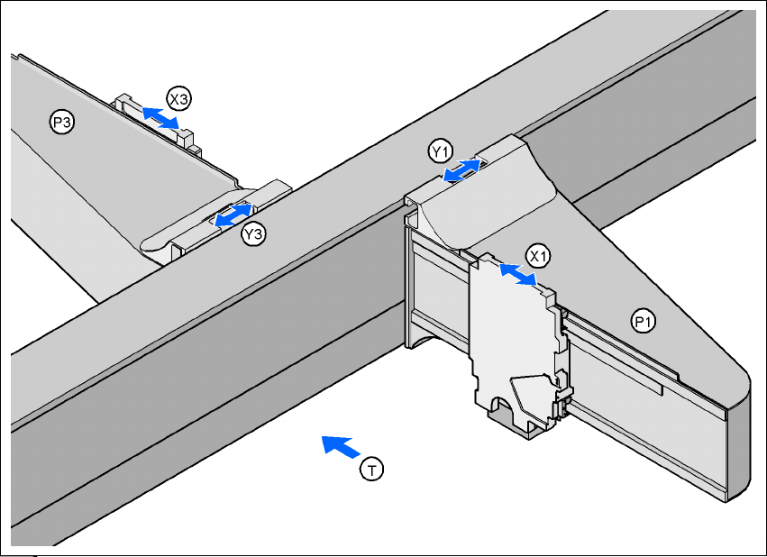
3.10.1 Position of the gantries for the HF placement machine
3
Fig. 3.10 - 1 Position of the gantries for the HF placement machine
3
P1 Gantry 1 3
X1 X axis, gantry 1 3
Y1 Y axis, gantry 1 3
P3 Gantry 3 3
X3 X axis, gantry 3 3
Y3 Y axis, gantry 3 3
(T) Direction of PCB transport
3
The gantry system consists of two functional groups 3
– X axis and
–Y axis
Placement area 2
Placement area 1
User manual SIPLACE HF series 3 Technical data
Software Version SR.50x.xx 01/2006 US Edition 3.10 Gantries
139
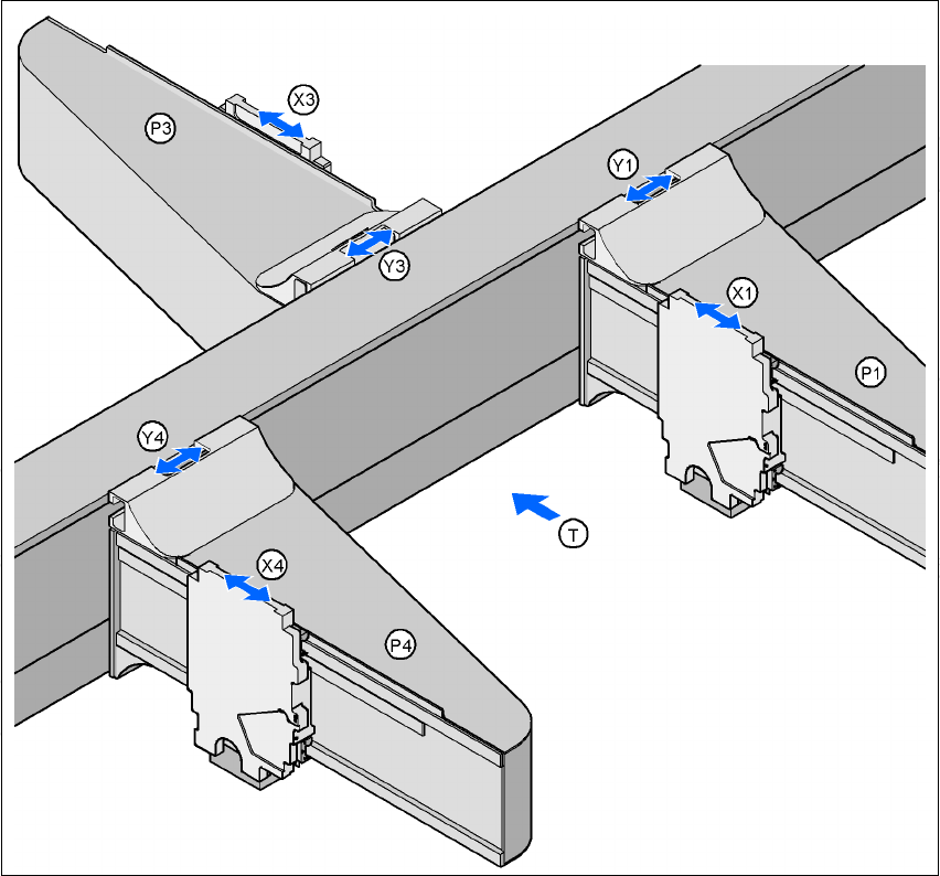
3.10.2 Position of the gantries for the HF/3 placement machine
3
Fig. 3.10 - 2 Position of the gantries for the HF/3 placement machine
3
P1 Gantry 1 3
X1 X axis, gantry 1 3
Y1 Y axis, gantry 1 3
P3 Gantry 3 3
X3 X axis, gantry 3 3
Y3 Y axis, gantry 3 3
P4 Gantry 4 3
X4 X axis, gantry 4 3
Y4 Y axis, gantry 4 3
(T) Direction of PCB transport
Placement area 2
Placement area 1
3 Technical data User manual SIPLACE HF series
3.10 Gantries Software Version SR.50x.xx 01/2006 US Edition
140
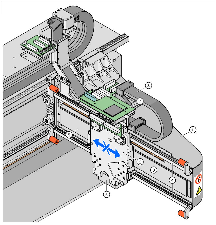
3.10.3 Structure of the X axis
3
Fig. 3.10 - 3 Structure of the X axis
(1) Gantry arm
(2) Head mount
(3) Linear distance measuring system
(4) Guide system
(5) Linear drive with permanent magnet
(6) Sub-gantry camera
(7) Head boards
(8) Cable and hose carrier