00193922-03.pdf - 第130页
3 Technical data User manual SIPLACE HF series 3.7 Placement heads S oftware Version SR.50x.x x 01/2006 US Edition 130 The DP ax is rotates the optical ly cente red compone nt to the desired pl acement a ngle. Th e ro- t…

User manual SIPLACE HF series 3 Technical data
Software Version SR.50x.xx 01/2006 US Edition 3.7 Placement heads
129
3.7.4.1 Description
This sophisticated placement head consists of two placement heads of the same type coupled to-
gether (twin head). Both heads work using the Pick&Place principle. The TwinHead is suitable for
processing particularly difficult or large components. Two components are picked up by the place-
ment head, optically centered on the way to the placement position and rotated into the necessary
placement angle. They are then placed gently and accurately onto the PCB with a controlled blast
of air. 3
New nozzles (type 5xx) have been developed for the TwinHead. It is also possible to fit an adapter
and then use type 4 nozzles for the Pick&Place head and type 8xx and 9xx nozzles for the Col-
lect&Place heads. 3
Checking and self-learning functions 3
The TwinHead's reliability can be further increased with various checking and self-learning func-
tions. 3
– For example, vacuum checks at the nozzles indicate whether the component was picked up
or set down correctly.
– High-resolution, intelligent vision modules, such as the fine-pitch and flip-chip vision modules,
identify and correct minute deviations from the desired component position, thus guarantee-
ing a correct placement position. The component cameras are permanently fixed to the ma-
chine frame.
– The component package form is also checked, and the component is not placed if the geo-
metric data thus determined differs from the programmed data.
– A force sensor measures and monitors the specified component placement forces.
– If the compressed air or power fails, the vertical axis (Z axis) is raised to a safe position in
order to prevent a head crash.
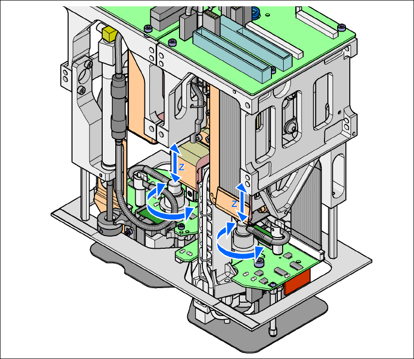
3.7.4.2 Description of the functions
The TwinHead consists of two Pick&Place heads that are coupled to one another, but are con-
trolled independently. Each head has two axes - the Z and the DP axis (see Fig. 3.7 - 8
). 3
The traversing path of the Z axis is detected via a high-resolution, linear incremental measuring
system. The Z axis performs a vertical movement. A linear motor raises and lowers the Z axis,
and components are picked up from feeder modules or trays and lowered onto the PCB. The
Z axis is an "intelligent axis". It "notes" the pick-up height for feeder modules and trays and the
placement height for each component. This can speed up the placement process. The pro-
grammed placement force is measured and monitored by a force sensor. 3
3 Technical data User manual SIPLACE HF series
3.7 Placement heads Software Version SR.50x.xx 01/2006 US Edition
130
The DP axis rotates the optically centered component to the desired placement angle. The ro-
tation axis is driven by a stepping motor. The motor shaft is designed as a sleeve. At the top end
is the incremental disk for angle analysis, while the nozzle holding device is at the bottom end. 3
The sequences of movements of the rotation and translation axes are controlled by control cir-
cuits. Position and speed sensors send the actual values for the axis movement to the axis con-
trol. The setpoint and actual values are compared and used to determine the force and speed
parameters for the servo amplifier, and thus the axis movement to be performed. 3
The vacuum values at the nozzle are constantly checked throughout the entire pick-up and
placement process in order to keep the placement error rate as low as possible. 3
3
Fig. 3.7 - 10 Description of the functions
3
User manual SIPLACE HF series 3 Technical data
Software Version SR.50x.xx 01/2006 US Edition 3.7 Placement heads
131
3.7.4.3 Technical data
3
3
3
*) Please note that the component range that can be placed is also affected by the pad geometry, the customer-specific
standards and the packaging tolerances.
**) If standard nozzles are used
Optical centering with Stationary P&P component vision
camera (type 22) 50 x 40
Stationary P&P component vision
camera (type 20) 8 x 8
Component range *) 0603 to SO, PLCC, QFP, BGA, special
components, bare dies, flip-chips
0201 to SO, PLCC, QFP, sockets,
plugs, BGA, special components,
bare dies, flip-chips, shields
Component specification
max. height
min. lead pitch
min. ball pitch
min. ball diameter
min. dimensions
max. dimensions
max. weight
25 mm (higher available on request)
0.4 mm
0.56 mm
0.32 mm
1.6 x 0.8 mm²
50 x 40 mm² (single measurement)
For use with two nozzles:
50 x 50 mm² or
69 x 10 mm ²
For use with one nozzle:
85 x 85 mm² or
125 x 10 mm²
Up to 200 x 125 mm² (with restrictions)
100 g **)
25 mm (higher available on request)
0.25 mm
0.14 mm
0.08 mm
0.6 x 0.3 mm²
8 x 8 mm² (single measurement)
100 g **)
Programmable set-down
force
1.0 N - 15 N 1.0 N - 15 N
Nozzle types 5 xx (standard)
4 xx + adapter
8 xx + adapter
9 xx + adapter
5 xx (standard)
4 xx + adapter
8 xx + adapter
9 xx + adapter
Nozzle spacing on the two
Pick&Place heads
70.8 mm 70.8 mm
X/Y accuracy ± 26 µm / 3 σ, ± 35 µm / 4 σ ± 22 µm / 3 σ, ± 30 µm / 4 σ
Angular accuracy ± 0.05° / 3 σ, ± 0.07° / 4 σ ± 0.05° / 3 σ, ± 0.07° / 4 σ