00193922-03.pdf - 第273页
User manual SIPLAC E HF series 6 Component handling Software Vers ion SR.50x.xx 01/2006 US Edition 6.3 Component trolley 273 imity s witches signal whet her the c omponent tr olley has been d ocked in correctl y . – The …
6 Component handling User manual SIPLACE HF series
6.3 Component trolley Software Version SR.50x.xx 01/2006 US Edition
272
PLEASE NOTE:
At external set-up positions, you will need an external power supply for the component trolley
(see section 6.3.5, page 278).
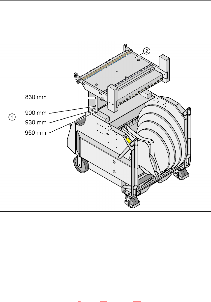
Fig. 6.3 - 2 Component trolley with a PCB transport height of 950 mm
6
(1) Holes in the guide columns for the transport heights of 830 to 950 mm
(2) Component trolley table
The design places considerable emphasis on ergonomics and safe operation.
– The trolleys move easily.
– No cables have to be plugged in to supply the component trolleys with power and com-
pressed air. The same applies to the communication interface.
– The component trolley is docked in/out the machine using a docking unit. A description of this
device can be found in chapter 5
, section 5.8, from page 240 onward. It is integrated into the
safety, supply and communication circuit or is disconnected from this circuit. Electronic prox-
User manual SIPLACE HF series 6 Component handling
Software Version SR.50x.xx 01/2006 US Edition 6.3 Component trolley
273
imity switches signal whether the component trolley has been docked in correctly.
– The component trolley is fixed so precisely to the placement machine that it is even suitable
for processing 0201 components.
– The component trolley can be adjusted to PCB transport heights of 830 mm, 900 mm,
930 mm and 950 mm in just a few simple actions.
– The tape container can hold tape reels with a diameter of up to 15" (optional up to 19").
– Every component trolley has a unique identification number.
6 Component handling User manual SIPLACE HF series
6.3 Component trolley Software Version SR.50x.xx 01/2006 US Edition
274
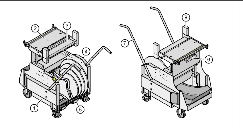
6.3.1 Structure of the component trolley
The component trolley essentially consists of the chassis, the component table for holding the
feeder modules, the communication unit, tape reel container and the waste container.
Fig. 6.3 - 3 Component trolley: front and back view
(1) Chassis
(2) Component feeder table
(3) Communication unit
(4) Tape reel container
(5) Waste tape container
(6) Interface for the main power supply, communication, the safety circuit and the compressed
air supply for the bulk case feeder module
(7) Handle
(8) Hand guard