Oxford-100-Manual.pdf - 第108页
PiasmaiabSystem100 Oxford Instruments Plasma Technology System Manual RF Generator panel ICP GENERATOR panel CRYO panel HELIUM BACKING panel Enter the required forward power. The forward power, reflected power, power ON/…
System
Manual
Stop
button
Pause
button
Jump
button
Oxford
Instruments
Plasma
Technology
Select
to
stop
the
current
process step.
Select
to
pause
the
current
process.
Select
tojump
to
the
next
process step.
PlasmalabSystem
100
Recipe message
field
Step
Time
fields
Log
Interval
fields
Process
status
field
Pump
to
Pressure
checkbox
Pressure fields
Ignore
Tolerances
checkbox
Hold
button
Displays
information
about
the
current
recipe, step, loaded
wafer
identity,
etc
..
Enter
the
required
step
time
in hours:minutes:seconds.
While
a process
is
running,
the
adjacent
field
displays
the
time
remaining
to
the
end
of
the
step.
Enter
the
interval
required
between
data
logging
events.
Indicates
the
process status;
either
Ready,
Auto
or
Manual
Select
to
create a
pumping
step. The system
will
pump
down
until
the
demanded
pressure
is
reached. The step
will
remain active
until
this
condition
is
met. Both
RF
Generators are
automatically
switched
off
during
the
step. (v' Indicates selected).
All
setpoints are
automatically
set
to
zero, except
for
base pressure.
Enter
the
required
Process
Chamber pressure
for
the
step. The
measured pressure
is
displayed
in
the
adjacent field.
Select
to
disable tolerance checking
during
the
current
step.
(V""
indicates selected).
NOTE:
RF
power
turns
on
immediately
without
waiting
for
flows
and
pressure
to
be established.
Used in
multi-step
recipes
to
keep
the
plasma
on
between
steps.
NOTES:
The
Hold
button
is
only
displayed
on
the
Process
Control page
when
a
recipe
is
loaded. The Hold
facility
can be selected
when
creating/editing
a process step using
the
Process
Editor
page.
When
running
the
recipe,
at
the
end
of
the
process
time
for
a process
step
without
the
Hold
button
selected, all process setpoints (chamber
pressure,
helium
backing pressure,
table
temperature,
RF
power,
rcp
power, gas
flow,
etc) are set
to
zero
(off)
before
starting
the
next
process step. This means
that
the
plasma
would
be extinguished
between
two
plasma process steps
if
the
Hold
button
were
not
selected.
When
running
the
recipe,
at
the
end
of
the
process
time
for
a process
step
with
the
Hold
button
selected, all process setpoints (chamber
pressure,
helium
backing pressure,
table
temperature,
RF
power,
ICP
power, gas
flow,
etc) are set
to
the
values
of
the
next
process step
to
run. This means
that
the
plasma remains
on
between
two
plasma
process steps
if
the
Hold
button
is
selected.
Printed: 22-Mar-06, 10:42
Operating
Instructions
Page
5-41
of
52
UC
Davis 94-721001
Issue
1:
March 06
PiasmaiabSystem100
Oxford
Instruments
Plasma
Technology
System Manual
RF
Generator
panel
ICP
GENERATOR
panel
CRYO panel
HELIUM
BACKING panel
Enter
the
required
forward
power.
The
forward
power, reflected
power,
power
ON/OFF status and
DC
bias are displayed.
Clicking
the
Set
Fwd
Power
button
toggles
the
demand
between
a
forward
power
set
point
and a
DC
bias set
point.
If
a
DC
bias demand
is
set,
the
RF
power
will
be varied
to
try
to
achieve
the
required
bias.
Use
this
facility
with
care:
if
the
plasma does
not
strike
or
if
the
DC
bias
cannot
be
read (by covering
the
table
with
insulator),
then
the
RF
power
will
increase
to
maximum.
Enter
the
required
forward
power.
The
forward
power, reflected
power,
ON/OFF status are displayed.
Enter
the
required
table
temperature.
The
current
table
temperature
is
displayed.
Enter
the
required
backing pressure. The
current
pressure (Torr) and
flow
rate
(sccm) are displayed. The open/closed status
of
the
control
valve
is
displayed.
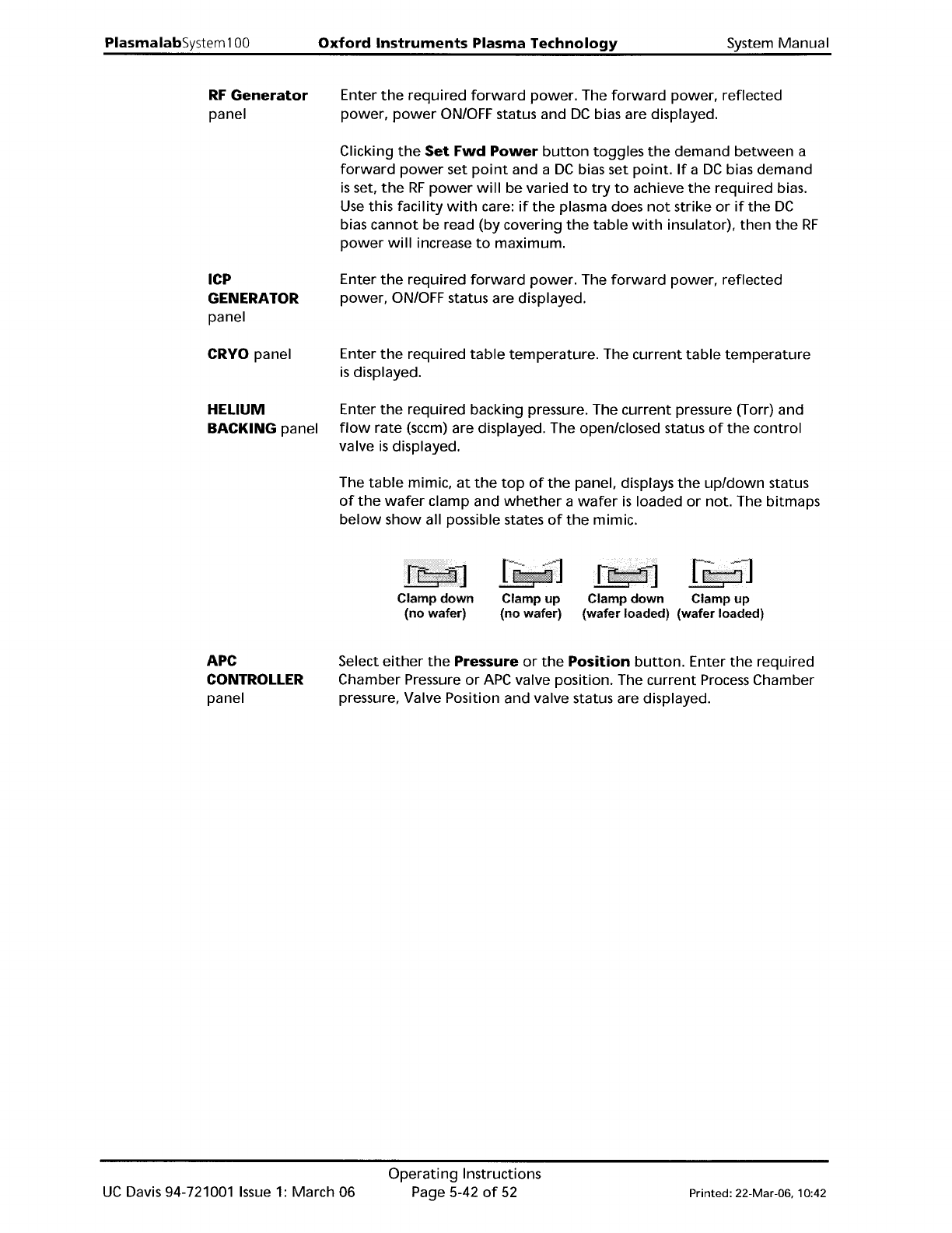
The
table
mimic,
at
the
top
of
the
panel, displays
the
up/down
status
of
the
wafer
clamp and
whether
a
wafer
is
loaded
or
not. The bitmaps
below
show
all possible states
of
the
mimic.
Clamp
down
(no wafer)
Fij!pdTI
Clamp
up
(no wafer)
Clamp
down
Clamp
up
(wafer loaded) (wafer loaded)
APC
CONTROLLER
panel
Select
either
the
Pressure
or
the
Position
button.
Enter
the
required
Chamber Pressure
or
APC
valve position. The
current
Process
Chamber
pressure, Valve Position and valve status are displayed.
UC
Davis 94-721001
Issue
1:
March 06
Operating
Instructions
Page 5-42
of
52
Printed: 22-Mar-06. 10:42
System
Manual
Oxford
Instruments
Plasma
Technology
PlasmalabSystem
100
LOW
PRESSURE
STRIKE panel
The
low
pressure strike
feature
allows plasma processing
at
low
pressures.
When
the
gas pressure
is
too
low,
it
is
not
possible
to
strike
a plasma;
however
it
is
possible
to
sustain a plasma
to
very
low
pressures once
it
has been
ignited.
This
software
feature
enables
the
user
to
raise
the
pressure
temporarily,
strike a plasma, and
automatically
reduce
the
pressure
to
the
desired
value
for
processing.
The
three
data fields and
their
effects are:
Strike
Pressure
field
DC bias
Minimum
field
Ramp
Rate
field
Enter
the
value in
mTorr
at
which
the
RF
should
turn
on and strike
the
plasma.
If
a zero
is
entered,
the
feature
is
disabled and
the
RF
will
turn
on once
the
pressure has stabilised
at
the
requested process
pressure.
Enter a positive
number
for
the
minimum
DC
bias
value expected once
the
plasma has struck. Enter
zero
if
DC
bias
cannot
be read because
the
substrate (and any
wafer
clamp)
completely
cover
the
electrode,
or
if
the
electrode has an insulating
coating. A
non-zero
value
is
used by
the
software
to
detect
if
the
plasma has been
properly
established.
If
a
zero
is
entered,
then
the
software
assumes
the
plasma has struck once
the
RF
reflected
power
goes
low.
Enter a
number
to
set
the
rate
at
which
the
pressure
is
reduced
from
the
strike
value
to
the
set
point.
The
higher
the
number
entered,
the
faster
the
transition
to
process conditions
will
be.
Note
that
too
high
a value can cause
the
plasma
to
go
out
if
the
plasma impedance changes faster
than
the
RF
matching
unit
can track.
Printed: 22-Mar-06, 10:42
Operating
Instructions
Page 5-43
of
52
UC
Davis 94-721001
Issue
1:
March 06