Oxford-100-Manual.pdf - 第244页
Plasma lab ICP 180 2. Services Oxford Instruments Plasma Technology Equipment Manual 2.1 Qualitative requirements The qualitative services requirements for the Plasma lab ICP 180 source are given in Appendix S - 'Se…

Equipment
Manual
Oxford
Instruments
Plasma
Technology
Plasma
lab
lep 180
1.
Health
and
Safety
For Health and Safety aspects
of
operating
and
maintaining
the
ICP
180 source,
refer
to
Section 1 - Health
and Safety
of
the
PiasmaiabSystem100 manual.
Printed: l8-Jan-DB, 8:44
ICP
180 Source
Page 3
of
26
Issue
3 : December 00
Plasma
lab
ICP
180
2. Services
Oxford
Instruments
Plasma
Technology
Equipment
Manual
2.1
Qualitative
requirements
The
qualitative
services requirements
for
the
Plasma
lab
ICP
180 source are given in
Appendix
S- 'Services
Specifications
for
Plasma
lab
and
lonfab
Systems'. This
document
gives generic
information
and
mandatory
requirements
for
all services.
2.2
Quantitative
requirements
2.2.1
Cooling
water
The source has
two
cooling
circuits:
14
inch
pipework
circuit
requiring
1
litrelminute
3/
8
inch
pipework
circuit
requiring
2
litreslminute
The
3/
8
inch
circuit
can be
put
in series
with
the
RF
generator
cooling
provided
the
minimum
flows
of
both
are satisfied.
Cooling
water
is
required
at
a
minimum
flow
rate
of
2
litreslminute
to
the
source. The
RF
generator
requires 4
litreslminute
(1200W)
or
8
litreslminute
(3000W).
2.2.2
Process gas
Process
gas supplies are
required
for
the
source and
for
the
process chamber. Types
of
gases and
their
flow
rates
depend
on
the
process application.
Normally
all gas
is
injected
at
the
top
of
the
source. A
few
processes (especially
PECVD
processes)
require
some
of
the
gas
to
be injected downstream.
2.2.3
RF
power
An
RF
generator
is
required
to
supply
power
to
the
automatch
unit.
The
RF
generator
should have an
output
impedance
of
50 ohms and a
minimum
power
rating
of
1200W.
The maximum
allowable
RF
power
input
to
the
automatch
unit
is
3kW.
2.2.4
Electrical
supply
The electrical supply
required
for
the
automatch
unit
are
is
24VDC
at
2A
maximum.
2.2.5
Extraction
The extraction collar
fitted
on
the
top
cover must be connected
to
an
extraction
system having a
minimum
flow
rate
of
1 m
3
/minute
at
60
Pa
extraction
pressure.
This
requirement
can be waived
for
alumina
tubes
provided
those
responsible
for
machine
safety
permit
it.
They should
perform
a risk assessment
which
considers
breaking
of
the
ICP
tube
during
processing.
The
requirement
cannot
be
waived
for
an
ICP
180
fitted
with
a
quartz
tube,
because UV emission
from
the
plasma
will
generate
ozone.
Issue
4:
January 06
ICP
180 Source
Page 4
of
26
Printed: 18-Jan-06, 8:44
Equipment
Manual
Oxford
Instruments
Plasma
Technology
Plasma
lab
fCP
180
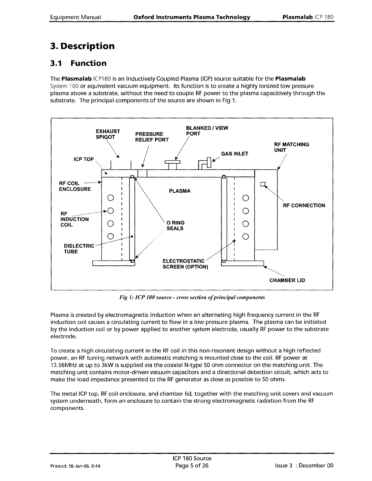
3. Description
3.1
Function
The
Plasma
lab
ICP180
is
an Inductively Coupled Plasma
(ICP)
source suitable
for
the
Plasma
lab
System
100
or
equivalent
vacuum
equipment.
Its
function
is
to
create a
highly
ionized
low
pressure
plasma above a substrate,
without
the
need
to
couple
RF
power
to
the
plasma capacitively
through
the
substrate. The principal components
of
the
source are
shown
in Fig
1.
RF MATCHING
UNIT
/
GAS INLET
~
BLANKED I VIEW
PORT
/
PRESSURE
RELIEF PORT
EXHAUST
SPIGOT
\
ICPTOP
RFCOIL
---
ENCLOSURE
PLASMA
0
0
RF
CONNECTION
RF
----_.--
,...0
0
-----
INDUCTION
0
o RING
0
COIL
SEALS
0
0
DIELECTRIC
TUBE
ELECTROSTATIC
SCREEN (OPTION)
CHAMBER LID
Fig 1: ICP 180 source - cross section ojprincipal components
Plasma
is
created by
electromagnetic
induction
when
an
alternating
high
frequency
current
in
the
RF
induction
coil causes a circulating
current
to
flow
in a
low
pressure plasma. The plasma can be
initiated
by
the
induction
coil
or
by
power
applied
to
another
system electrode, usually
RF
power
to
the
substrate
electrode.
To create a
high
circulating
current
in
the
RF
coil
in
this
non-resonant
design
without
a
high
reflected
power, an
RF
tuning
network
with
automatic
matching
is
mounted
close
to
the
coil.
RF
power
at
13.56MHz
at
up
to
3kW
is
supplied via
the
coaxial N-type 50
ohm
connector on
the
matching
unit.
The
matching
unit
contains
motor-driven
vacuum capacitors and a
directional
detection
circuit,
which
acts
to
make
the
load impedance presented
to
the
RF
generator
as
close
as
possible
to
50 ohms.
The
metal
ICP
top,
RF
coil enclosure, and chamber lid,
together
with
the
matching
unit
covers and vacuum
system
underneath,
form
an enclosure
to
contain
the
strong
electromagnetic
radiation
from
the
RF
components.
Printed: 18-Jan-06. 8:44
ICP
180 Source
Page 5
of
26
Issue
3 : December 00