Oxford-100-Manual.pdf - 第284页
All OIPT Systems Oxford Instruments Plasma Technology System Manual 6.2 Link Settings Incorrect link settings can cause the AMU to malfunction. The factory default settings are given in the following table: Air Low Power…
System
Manual
Oxford
Instruments
Plasma
Technology
All
OIPT Systems
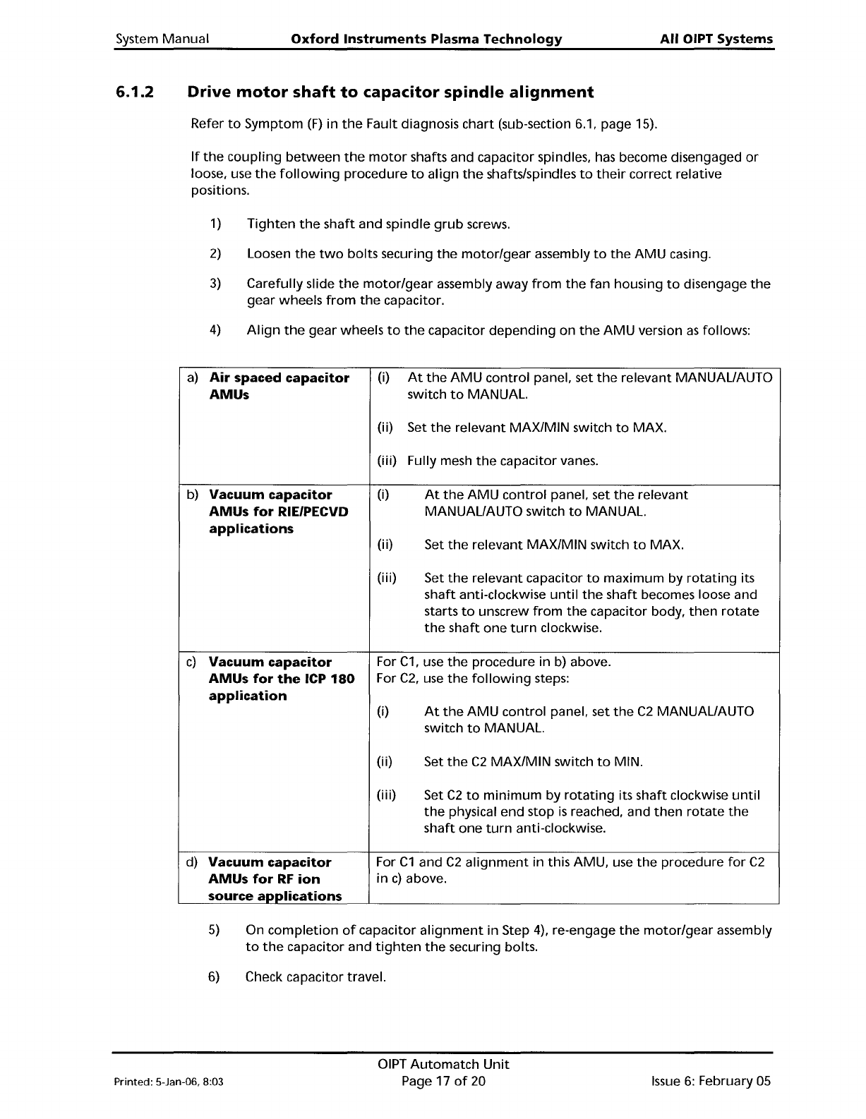
6.1.2
Drive
motor
shaft
to
capacitor
spindle
alignment
Refer
to
Symptom
(F)
in
the
Fault diagnosis
chart
(sub-section 6.1, page 15).
If
the
coupling
between
the
motor
shafts and capacitor spindles,
has
become disengaged
or
loose, use
the
following
procedure
to
align
the
shafts/spindles
to
their
correct relative
positions.
1)
Tighten
the
shaft
and spindle
grub
screws.
2)
Loosen
the
two
bolts
securing
the
motor/gear
assembly
to
the
AMU
casing.
3)
Carefully slide
the
motor/gear
assembly
away
from
the
fan
housing
to
disengage
the
gear wheels
from
the
capacitor.
4)
Align
the
gear wheels
to
the
capacitor
depending
on
the
AMU
version
as
follows:
a)
Air
spaced
capacitor
(i)
At
the
AMU
control
panel, set
the
relevant MANUAL/AUTO
AMUs
switch
to
MANUAL.
(i
i)
Set
the
relevant
MAX/MIN
switch
to
MAX.
(iii)
Fully mesh
the
capacitor vanes.
b)
Vacuum
capacitor
(i)
At
the
AMU
control
panel, set
the
relevant
AMUs
for
RIE/PECVD
MANUAL/AUTO switch
to
MANUAL.
applications
(i
i)
Set
the
relevant
MAX/MIN
switch
to
MAX.
(i
i
i)
Set
the
relevant capacitor
to
maximum
by
rotating
its
shaft
anti-clockwise
until
the
shaft
becomes loose and
starts
to
unscrew
from
the
capacitor body,
then
rotate
the
shaft
one
turn
clockwise.
c)
Vacuum
capacitor
For
C1,
use
the
procedure in
b)
above.
AMUs
for
the
ICP
180
For
C2,
use
the
following
steps:
application
(i)
At
the
AMU
control
panel, set
the
C2
MANUAL/AUTO
switch
to
MANUAL.
(i
i)
Set
the
C2
MAX/MIN
switch
to
MIN.
(i
i
i)
Set
C2
to
minimum
by
rotating
its
shaft
clockwise
until
the
physical end stop
is
reached, and
then
rotate
the
shaft
one
turn
anti-clockwise.
d)
Vacuum
capacitor
For
C1
and
C2
alignment
in this AMU, use
the
procedure
for
C2
AMUs
for
RF
ion
in
c)
above.
source
applications
5)
On
completion
of
capacitor
alignment
in Step 4), re-engage
the
motor/gear
assembly
to
the
capacitor and
tighten
the
securing bolts.
6)
Check capacitor travel.
Printed: 5-Jan-06, 8:03
OIPT
Automatch
Unit
Page 17
of
20
Issue
6:
February
05
All
OIPT Systems
Oxford
Instruments
Plasma
Technology
System Manual
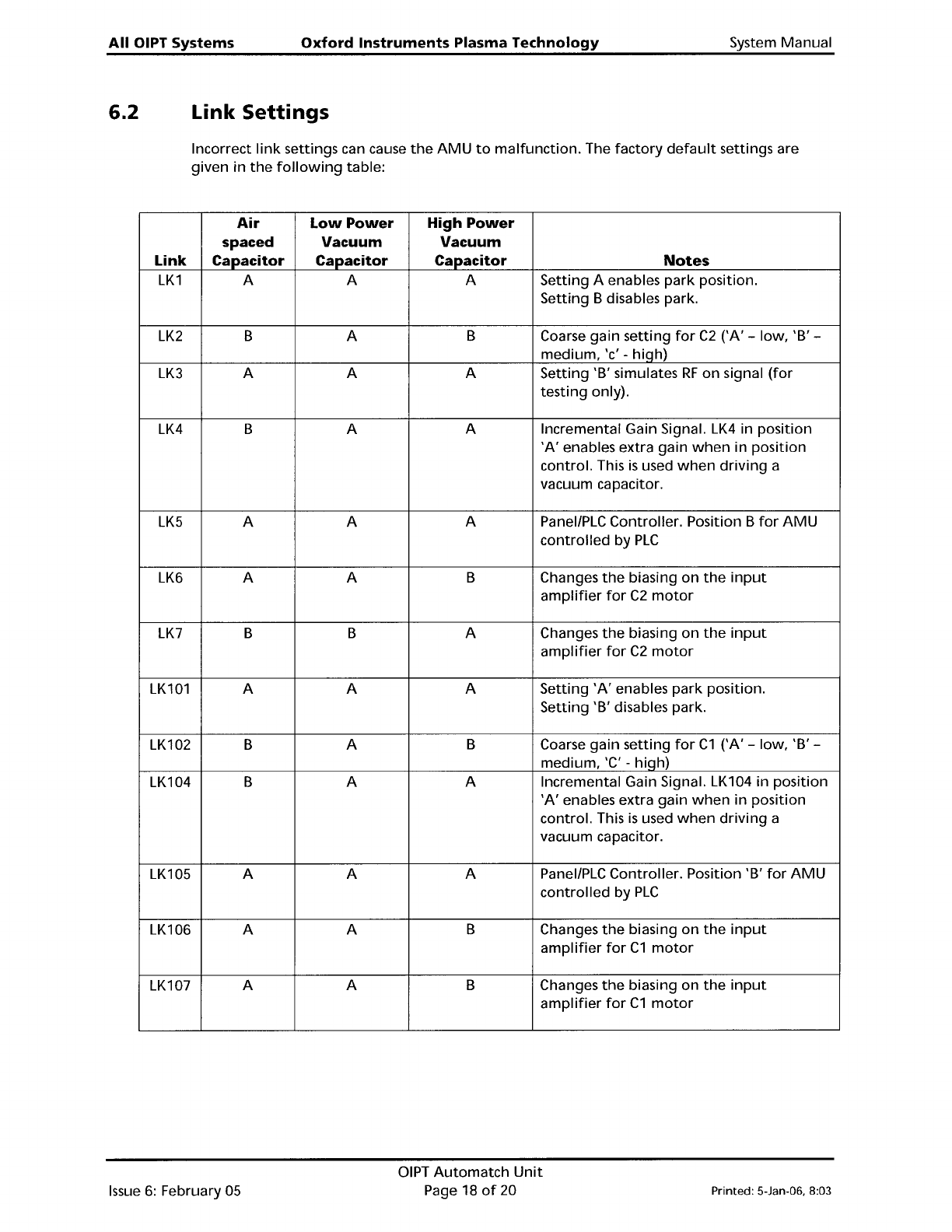
6.2 Link
Settings
Incorrect
link
settings can cause
the
AMU
to
malfunction.
The
factory
default
settings are
given
in
the
following
table:
Air
Low
Power
High
Power
spaced
Vacuum
Vacuum
Link
Capacitor Capacitor
Capacitor
Notes
LK1
A A A Setting A enables
park
position.
Setting B disables park.
LK2
B A B
Coarse gain setting
for
C2
CA' - low, 'B' -
medium, 'c'
- hiqh)
LK3
A A A Setting 'B' simulates
RF
on
signal
(for
testing
only).
LK4
B A A
Incremental Gain Signal.
LK4
in position
'A'
enables extra gain
when
in position
control. This
is
used
when
driving
a
vacuum capacitor.
LK5
A A
A PanellPLC Controller. Position B
for
AMU
controlled
by
PLC
LK6
A
A B Changes
the
biasing
on
the
input
amplifier
for
C2
motor
LK7
B B A
Changes
the
biasing
on
the
input
amplifier
for
C2
motor
LK101
A A A
Setting
'A'
enables
park
position.
Setting 'B' disables park.
LK102 B A
B Coarse gain setting
for
C1
CA' - low, 'B' -
medium, 'C' - hiqh)
LK104 B
A A
Incremental Gain Signal. LK104 in position
'A'
enables extra gain
when
in
position
control. This
is
used
when
driving
a
vacuum capacitor.
LK105 A A A
PanellPLC Controller. Position 'B'
for
AMU
controlled
by
PLC
LK106 A A B
Changes
the
biasing
on
the
input
amplifier
for
C1
motor
LK107
A A B
Changes
the
biasing on
the
input
amplifier
for
C1
motor
Issue
6:
February 05
DIPT
Automatch
Unit
Page 18
of
20
Printed: 5-Jan-06, 8:03
System
Manual
Oxford
Instruments
Plasma
Technology
All OIPT Systems
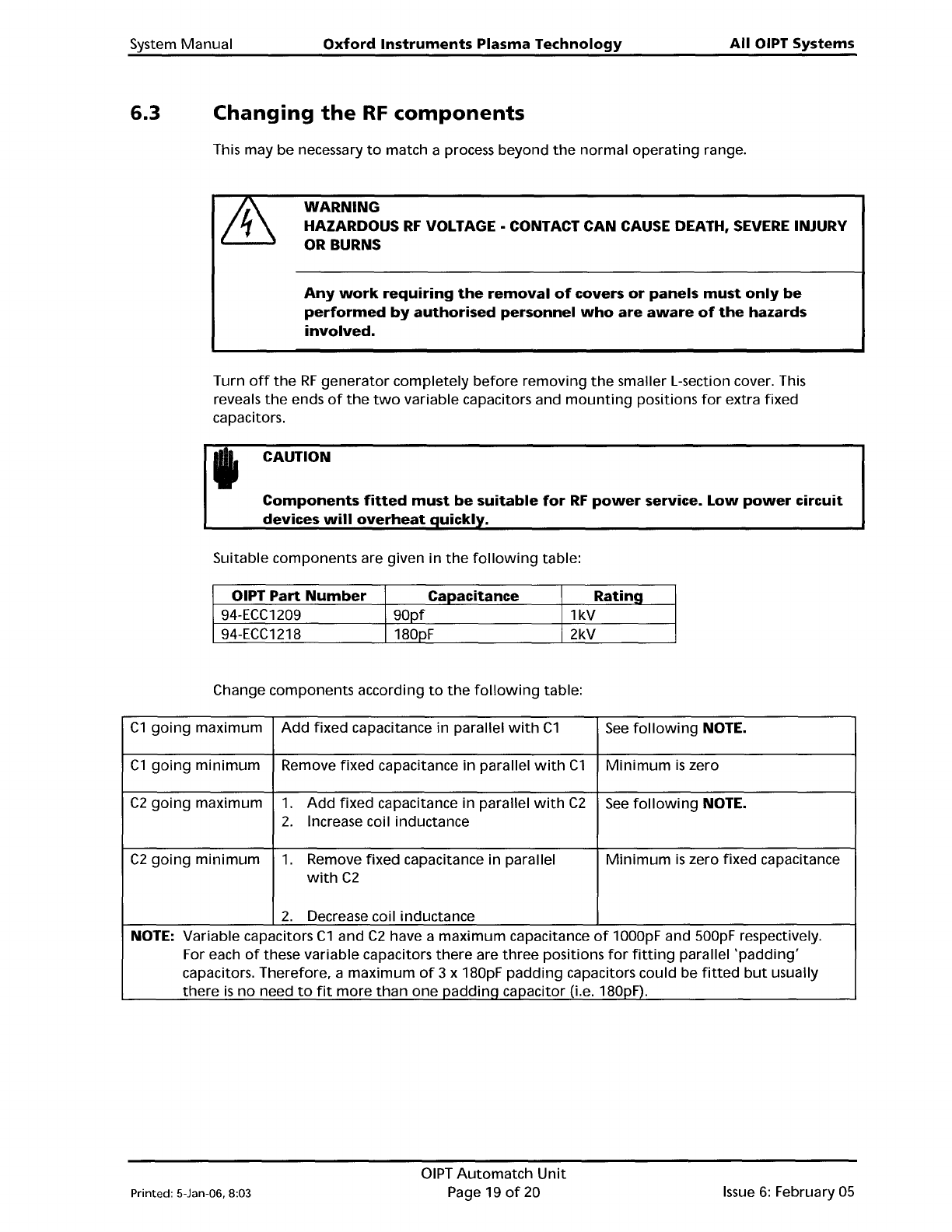
6.3
Changing
the
RF
components
This may
be
necessary
to
match a process beyond
the
normal
operating
range.
WARNING
HAZARDOUS
RF
VOLTAGE·
CONTACT CAN CAUSE DEATH,
SEVERE
INJURY
OR BURNS
Any
work
requiring
the
removal
of
covers
or
panels
must
only
be
performed
by
authorised
personnel
who
are
aware
of
the
hazards
involved.
Turn
off
the
RF
generator
completely
before
removing
the
smaller L-section cover. This
reveals
the
ends
of
the
two
variable capacitors and
mounting
positions
for
extra fixed
capacitors.
CAUTION
Components
fitted
must
be
suitable
for
RF
power
service.
Low
power
circuit
devices
will
overheat
uickl .
Suitable components are given
in
the
following
table:
OIPT
Part
Number
Capacitance
Rating
94-ECC1209
90pf
1kV
94-ECC1218
180pF 2kV
Change components according
to
the
following
table:
C1
going
maximum
Add
fixed
capacitance in parallel
with
C1
See
following
NOTE.
C1
going
minimum
Remove
fixed
capacitance
in
parallel
with
C1
Minimum
is
zero
C2
going
maximum
1.
Add
fixed
capacitance in parallel
with
C2
See
following
NOTE.
2.
Increase coil inductance
C2
going
minimum
1.
Remove
fixed
capacitance in parallel
Minimum
is
zero fixed capacitance
with
C2
2.
Decrease coil inductance
NOTE: Variable capacitors
C1
and
C2
have a
maximum
capacitance
of
1000pF and 500pF respectively.
For each
of
these variable capacitors
there
are
three
positions
for
fitting
parallel
'padding'
capacitors. Therefore, a
maximum
of
3 x 180pF
padding
capacitors could be
fitted
but
usually
there
is
no
need
to
fit
more
than
one
paddinq
capacitor (i.e. 180pF).
Printed: 5-Jan-06, 8:03
DIPT
Automatch
Unit
Page 19
of
20
Issue
6:
February
05