Oxford-100-Manual.pdf - 第50页
Plasmalab System 100 Oxford Instruments Plasma Technology System Manual 3.9 Gas handling system WARNING CONTACT WITH TOXIC GASES CAN CAUSE DEATH OR SERIOUS INJURY. USERS SHOULD PERFORM THEIR OWN RISK ASSESSMENT OF HAZARD…
System
Manual
Oxford
Instruments
Plasma
Technology
Plasma
lab
System
100
N,
Chamber
wi'nt,--I/
-
......
PROCESS CHAMBER
Turbo
purge
valve
...............
SEE NOTE 2
N,
Backing
valve
Load
lock
vent
Turbo
Pump
Controller
Pirani
gauge
Isolating
valve
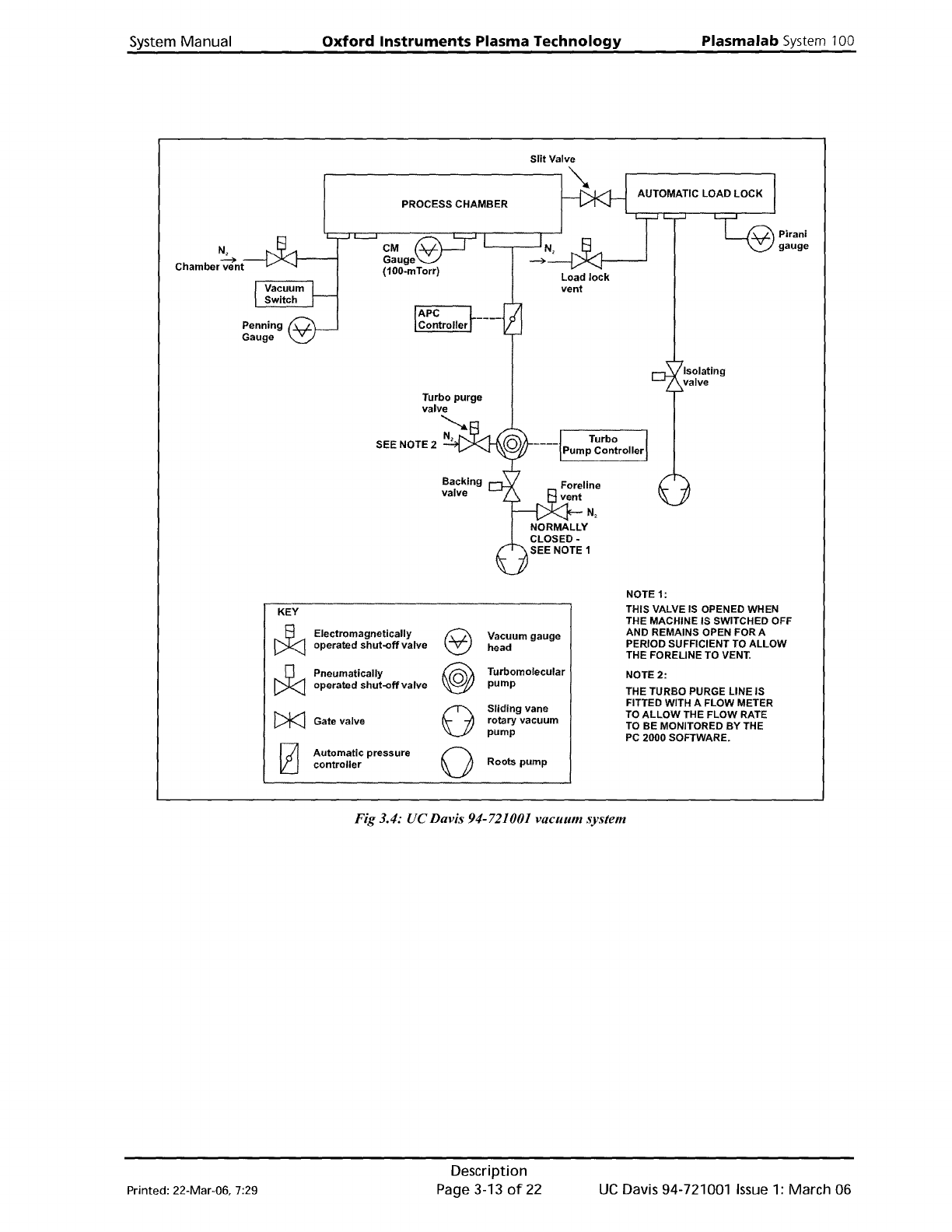
NOTE 1:
KEY
THIS VALVE
IS
OPENED WHEN
J:J
THE MACHINE IS SWITCHED OFF
Electromagnetically
e
Vacuum gauge
AND REMAINS OPEN FOR A
operated
shut-off
valve
head
PERIOD SUFFICIENT
TO
ALLOW
THE FORELINE TO
VENT.
~
Pneumatically
@
Turbomolecular
NOTE
2:
operated
shut-off
valve
pump
THE TURBO PURGE LINE IS
0
Sliding
vane
FITTED WITH A FLOW METER
[)k]
TO
ALLOW
THE FLOW RATE
Gate valve
rotary vacuum
TO
BE MONITORED
BY
THE
pump
PC
2000 SOFTWARE.
[2]
Automatic
pressure
0
Roots
pump
controller
Fig 3.4: UC Davis 94-721001 vacuum system
Printed: 22-Mar-06, 7:29
Description
Page 3-13
of
22
UC
Davis 94-721001
Issue
1:
March 06
Plasmalab
System
100
Oxford
Instruments
Plasma
Technology
System
Manual
3.9
Gas
handling
system
WARNING
CONTACT WITH TOXIC GASES CAN CAUSE DEATH OR SERIOUS INJURY.
USERS SHOULD PERFORM THEIR
OWN
RISK ASSESSMENT
OF
HAZARDOUS GASES
TO
BE
USED
ON
THE SYSTEM.
BEFORE VENTING THE PROCESS CHAMBER, ALWAYS ENSURE THAT THE SYSTEM IS
ADEQUATELY PURGED
AND
PUMPED;
SEE
'VENTING
THE
SYSTEM' IN SECTION 5
OF
THIS
MANUAL.
3.9.1
94-81-9-51/8
Gas
pod
(PLC
version)
The purpose
of
the
gas
pod
is
to
feed a
mixture
of
process
gases,
at
specified
flow
rates,
to
the
process chamber. Selection
of
gases and
flow
rates are
determined
by
the
system
controller.
A 'clean gas'
line
can
be
incorporated
to
feed an etch gas
mixture
into
the
process
chamber
to
remove process residues.
The gas pod, shown
in
Fig 3.5, comprises a steel
case
with
a removable cover.
An
extraction
collar
at
the
top
of
the
case
enables any leaked gas
to
be safely removed by a
laboratory
extraction
system. The back panel
of
the
case
is
fitted
with
fixing
holes
for
wall
or
frame
mounting.
UC
Davis 94-721001
Issue
1:
March 06
Description
Page 3-14
of
22
Printed: 22-Mar-06, 7:29
System
Manual
Oxford
Instruments
Plasma
Technology
Plasma
lab
System 100
GAS POD
PCB
CONTROL
CABLE
FROM
PLC
IPCB
\
SIX-WAYSMC
ASSEMBLY
GAS POD COVER
INTERLOCK MICROSWITCH
100MM EXTRACTION
COLLAR
PROCESS GAS
OUT
TO
CHAMBER
'CLEAN
GAS'
LINE
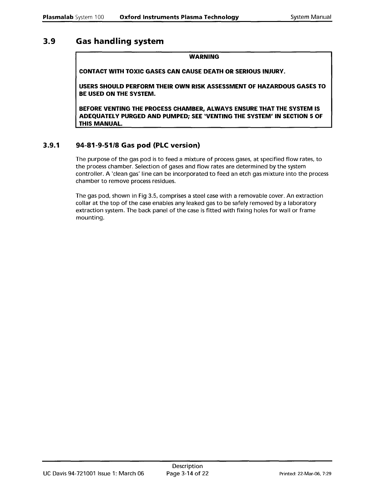
Fig 3.5: 94-81-9-51 Gas
pod
The
case
incorporates stations
for
up
to
six gas lines. The
outputs
from
the
gas lines are fed
into
a
common
manifold
which
is
connected
to
the
process chamber gas line. Pneumatically
operated
shut-off
valves
in
each gas
line
are driven
by
associated
SMC
valves,
powered
by
compressed
air
and
controlled
by
signals
from
the
system
controller.
A separate
SMC
valve,
controlled
by
an
interlock
microswitch, prevents
the
opening
of
any gas
shut-off
valve
when
the
case
cover
is
not
fitted,
or
when
either
of
the
system
interlock
lines are open.
The
Gas
Pod
PCB
receives signals
from
the
system
controller,
to
control
the
SMC
valves, and
the
Mass Flow Controllers (MFC)
fitted
in
the
gas lines. For a circuit
diagram
of
the
Gas
Pod
PCB,
refer
to
drawing
SE81
015942 in
Volume
2
of
this manual.
The 'clean gas'
line
flow
rate
can be set
either
manually
by a variable valve
(as
shown in Fig
3.5)
or
by
an
MFC.
Note
that
the
'clean gas'
is
usually supplied
from
a cylinder
containing
the
required
gas
mixture.
An
alternative
method
is
to
mix separate gases
in
optional
additional
gas lines.
Printed: 22-Mar-06, 7:29
Description
Page 3-15
of
22
UC
Davis 94-721001
Issue
1: March 06