Oxford-100-Manual.pdf - 第138页
PlasmalabSystem 1 00 Oxford Instruments Plasma Technology System Manual WARNING BEFORE PROCEEDING WITH ANY MAINTENANCE WORK, READ SECTION 1 - HEALTH AND SAFETY. ORING Quartz -=$25" TABLE SUPPORT TUBE ==;;;;;;;;;;;;;…
System
Manual
Oxford
Instruments
Plasma Technology
WARNING
PiasmaiabSystem100
BEFORE
PROCEEDING WITH
ANY
MAINTENANCE WORK, READ SECTION
1·
HEALTH
AND
SAFETY.
j)
If
it
should become necessary
to
change
from
PFPE
to
mineral oil
lubrication
or
vice
versa,
the
pump
must
be
completely
disassembled, freed
of
lubricant
and
fitted
with
new
gaskets and vanes.
k)
At
temperatures
over 350
0
C,
hazardous gaseous
decomposition
products are
formed.
Therefore
do
not
smoke
in
rooms
where
PFPE
is
used, and make sure
that
no
tobacco comes
into
contact
with
PFPE.
I)
When
handling
PFPE,
protective
clothing
must
be
used.
m) Do
not
mix
PFPE
with
used oil. Dispose
of
them
separately.
n)
PFPE
is
normally
odourless and colourless. Cloudiness
or
odour
is
a sign
of
contamination.
6.11.3
6.12
Hydrocarbon
lubricants
Where
mineral oils are used,
the
rate
of
oil
deterioration
for
a
particular
pump
and process
should
be
established
at
an early stage, and oil changes based
upon
this
information.
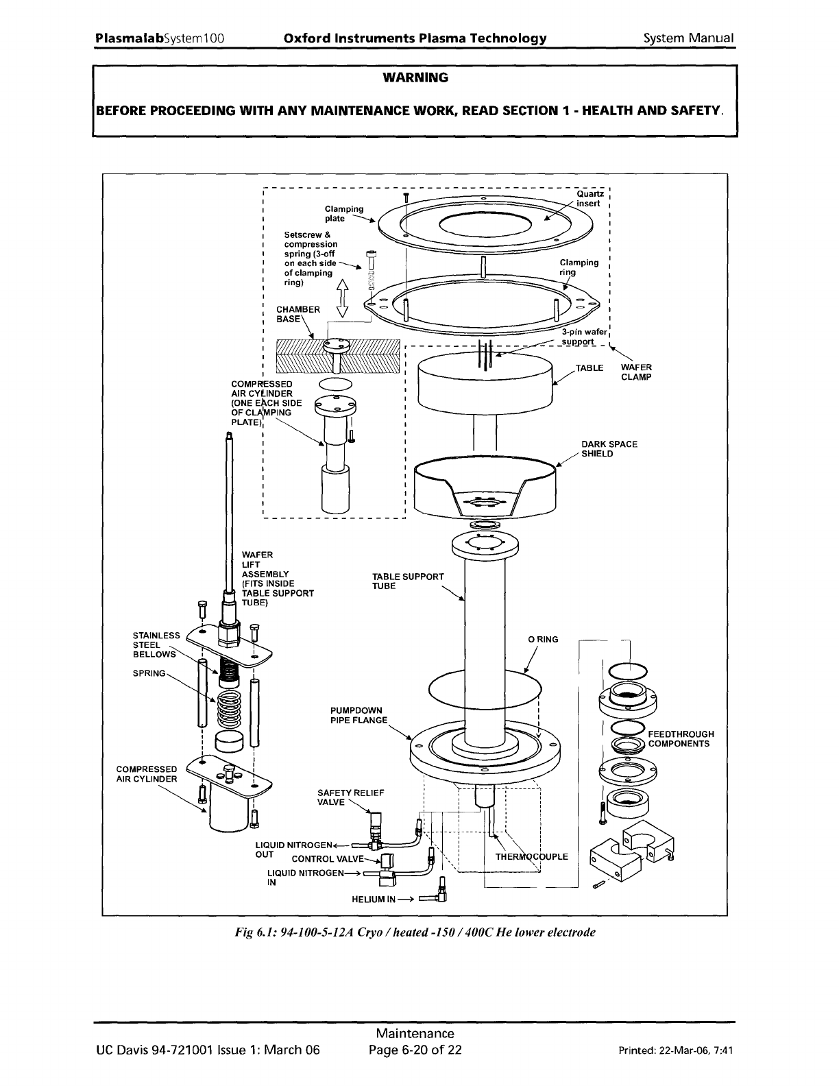
94-100-5-12A
Cryo
I
heated
-150
1400C
He
lower
electrode
wafer
clamping
plate
changeover
procedure
Before carrying
out
a process, in
the
process chamber
on
a
wafer
which
is
a
different
size
to
that
last processed,
it
is
necessary
to
fit
the
correct
type
of
clamping plate. Clamping plates
are available
for
various sized wafers.
To change
the
clamping plate, use
the
following
procedure
(refer
to
Fig 6.1, page 6-20):
6)
If
necessary,
vent
the
process chamber.
7)
Open
the
process chamber lid.
8)
Wearing
powder-free
gloves, unscrew
the
three
clamping
plate
securing screws
then
remove
the
clamping
plate
from
the
process chamber and place on a clean surface.
9)
Take
the
replacement
clamping
plate
and
mount
it
on
the
three
supporting
pillars
then
insert and
tighten
the
three
securing screws.
10) Close
the
process chamber lid.
Printed: 22-Mar-06,
7:41
Maintenance
Page 6-19
of
22
UC
Davis 94-721001
Issue
1:
March 06
PlasmalabSystem
100
Oxford
Instruments Plasma Technology
System Manual
WARNING
BEFORE
PROCEEDING WITH
ANY
MAINTENANCE WORK, READ SECTION 1 - HEALTH
AND
SAFETY.
ORING
Quartz
-=$25"
TABLE SUPPORT
TUBE
==;;;;;;;;;;;;;;:;;;;;;==
3-pin
wafer
'TTTTTT7T77TTn
_ _ _ s!'
p.PQrL
_ ,
TABLE WAFER
CLAMP
PUMPDOWN
PIPE FLANGE
WAFER
LIFT
ASSEMBLY
(FITS INSIDE
TABLE SUPPORT
TUBE)
---
-
--
-
-:-
---- - -
~~
, , '
I I , I
I I , I
LIQUID
NITROGEN+--r--l'I"1'l-=--~
,i
....
~-<
I
OUT CONTROL
VALVE~
~
\",1
THER~~PUPLE
~~QUID
NITROGEN~~
D
~--
---->
HELIUMIN~
c::::::elIi
COMP ESSED
AIR CYLINDER
(ONE
EACH SIDE
OFC~MPING
PLATE)
~
Fig 6.1: 94-100-5-12A Cryo I heated-150
1400C
He lower electrode
UC
Davis 94-721001 Issue
1:
March 06
Maintenance
Page
6-20
of
22
Printed: 22-Mar-06,
7:41
System
Manual
Oxford
Instruments
Plasma Technology
WARNING
PlasmalabSystem
100
BEFORE
PROCEEDING WITH
ANY
MAINTENANCE WORK, READ SECTION 1 - HEALTH
AND
SAFETY.
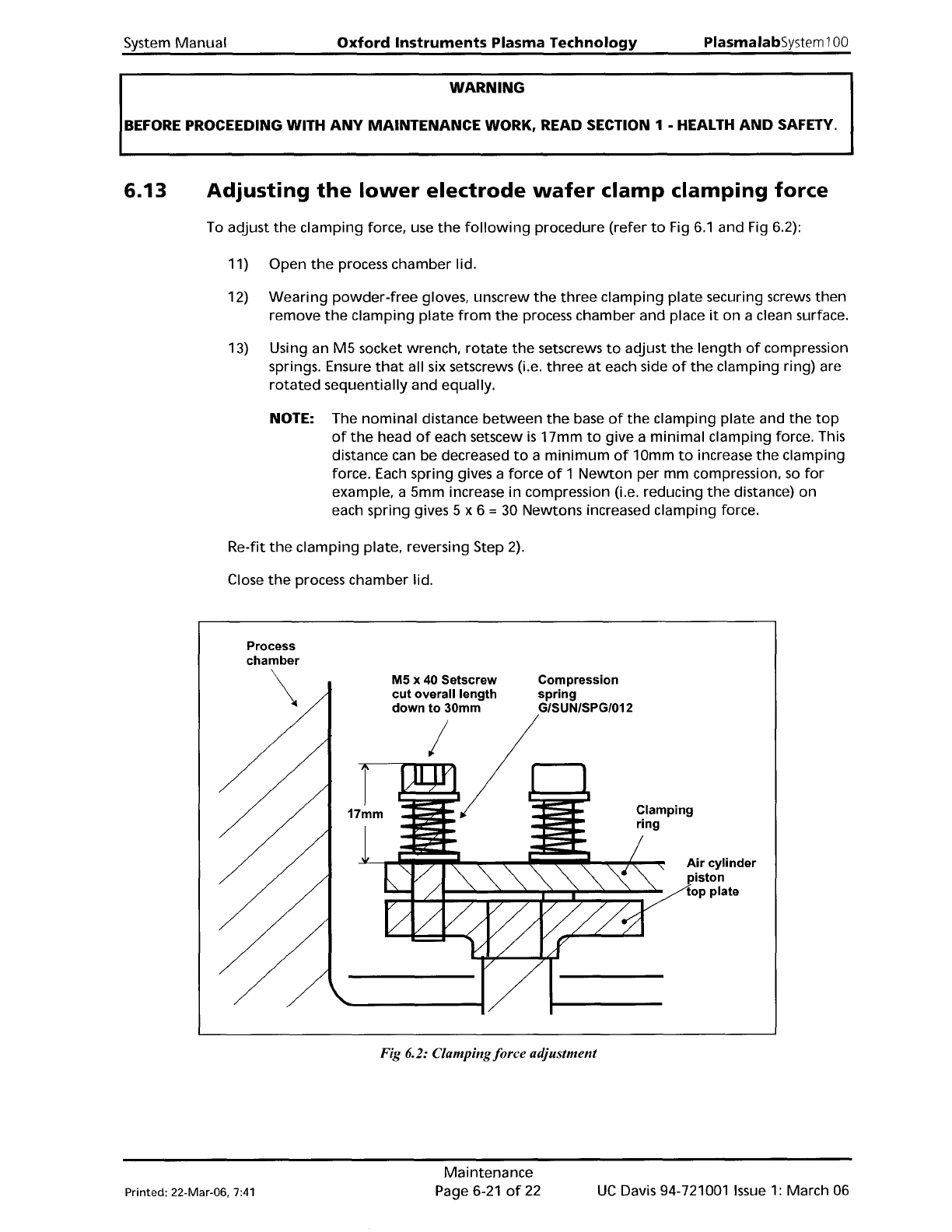
6.13
Adjusting
the
lower
electrode
wafer
clamp
clamping
force
To adjust
the
clamping
force, use
the
following
procedure
(refer
to
Fig
6.1
and Fig 6.2):
11) Open
the
process chamber lid.
12)
Wearing
powder-free
gloves, unscrew
the
three
clamping
plate
securing screws
then
remove
the
clamping
plate
from
the
process chamber and place
it
on a clean surface.
13) Using an
M5
socket wrench,
rotate
the
setscrews
to
adjust
the
length
of
compression
springs. Ensure
that
all six setscrews (i.e.
three
at
each side
of
the
clamping ring) are
rotated
sequentially
and
equally.
NOTE: The
nominal
distance
between
the
base
of
the
clamping
plate
and
the
top
of
the
head
of
each setscew
is
17mm
to
give a
minimal
clamping force. This
distance can be decreased
to
a
minimum
of
10mm
to
increase
the
clamping
force. Each spring gives a force
of
1
Newton
per mm compression.
so
for
example. a 5mm increase
in
compression (i.e. reducing
the
distance)
on
each spring gives 5 x 6 = 30 Newtons increased clamping force.
Re-fit
the
clamping
plate. reversing Step
2).
Close
the
process chamber lid.
Process
chamber
\
M5 x 40 Setscrew
cut overall length
down to 30mm
I
Compression
spring
G/SUN/SPG/012
Clamping
ring
Air cylinder
piston
top plate
Fig 6.2: Clampingforce adjustment
Printed: 22-Mar-06,
7:41
Maintenance
Page 6-21
of
22
UC
Davis 94-721001
Issue
1:
March 06