Oxford-100-Manual.pdf - 第251页
Equipment Manual 4. Installation Oxford Instruments Plasma Technology Plasma lab rcp 180 & WARNING This section applies if the Plasma lab IC P180 source is supplied as an upgrade, or as an exchangeable plasma source.…
Plasma
lab
Ie
P180
Operating
window
Oxford
Instruments Plasma Technology Equipment Manual
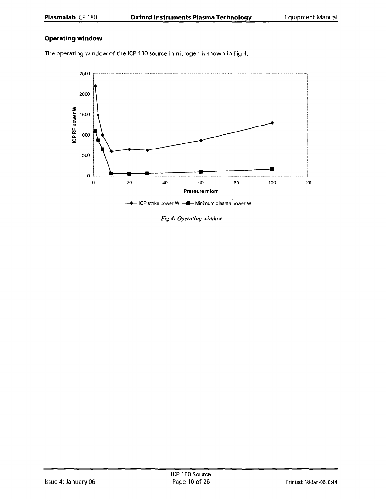
The
operating
window
of
the
ICP
180 source in
nitrogen
is
shown in Fig
4.
2500
2000
:!:
..
1500
Gl
~
0
Q.
U.
~
1000
ll.
!d
500
Pressure
mtorr
i
-+-ICP
strike power W _ Minimum plasma power W
Fig 4: Operating window
Issue
4:
January 06
ICP
180 Source
Page 10
of
26
Printed: 18-Jan-06, 8:44
Equipment
Manual
4.
Installation
Oxford
Instruments
Plasma
Technology
Plasma
lab
rcp
180
&
WARNING
This section applies
if
the
Plasma
lab
IC
P180 source
is
supplied
as
an upgrade,
or
as
an exchangeable
plasma source.
The ICP180
is
installed
as
the
entire
top
lid
to
a
Plasma
lab
System 100,
with
a vacuum 0
ring
on
the
underside
of
the
ICP180 chamber lid. The chamber
lid
is
secured
by
hinges
which
enable
access
to
the
process chamber
interior
for
maintenance.
PINCH POINT -
WHEN
THE CHAMBER LID IS OPENED OR CLOSED, LIMBS,
FINGERS
ETC
CAN
BECOME TRAPPED BETWEEN THE LID
AND
THE PROCESS
CHAMBER BASE RESULTING
IN
SEVERE INJURY.
J----------j
Ensure
that
all
personnel
are
kept
clear
of
the
chamber
lid
when
it
is
opened
or
closed.
When
opening
or
closing
the
chamber
lid,
ensure
that
both
of
your
hands
are
kept
clear
of
the
pinch
point.
When
the
process
chamber
lid
is
to
be
kept
in
its
raised
position
for
prolonged
periods,
ensure
that
it
is
held
safely
in
its
open
position
without
relying
entirely
on
the
gas
support
struts.
After
mechanical
mounting,
connect
the
services
detailed
in
Section 2
of
this manual.
The
RF
generator
services should be connected according
to
the
manufacturer's
manual supplied
with
the
generator.
Printed: 18-Jan-06. 8:44
ICP
180 Source
Page
11
of
26
Issue
3 : December 00
Plasma
lab
ICP
180
Oxford
Instruments
Plasma
Technology
Equipment
Manual
5.
Operating
Instructions
5.1
Introduction
WARNING
BEFORE POWERING UP
THE
SOURCE, ENSURE THAT
ALL
COVERS
AND
SCREENS ARE
FITTED CORRECTLY.
DO
NOT REMOVE THE COVERS OR SCREENS WHILST
THE
SOURCE IS UNDER
VACUUM.
The
only
controls
on
the
Plasmalab
IC
P180 are
the
Automatch
Unit
(AMU)
control
switches,
mounted
on
the
system console.
5.1.1
Manual
adjustment
of
the
Automatch
Unit
NOTE:
The
following
text
refers
to
systems
fitted
with
an
Automatch
Unit
manual
adjustment
panel.
For
systems
having
software
control
of
the
Automatch
Unit,
refer
to
Section
5
(Operating
Instructions)
of
your
system
manual
and
the
Automatch
Unit's
Equipment
Manual.
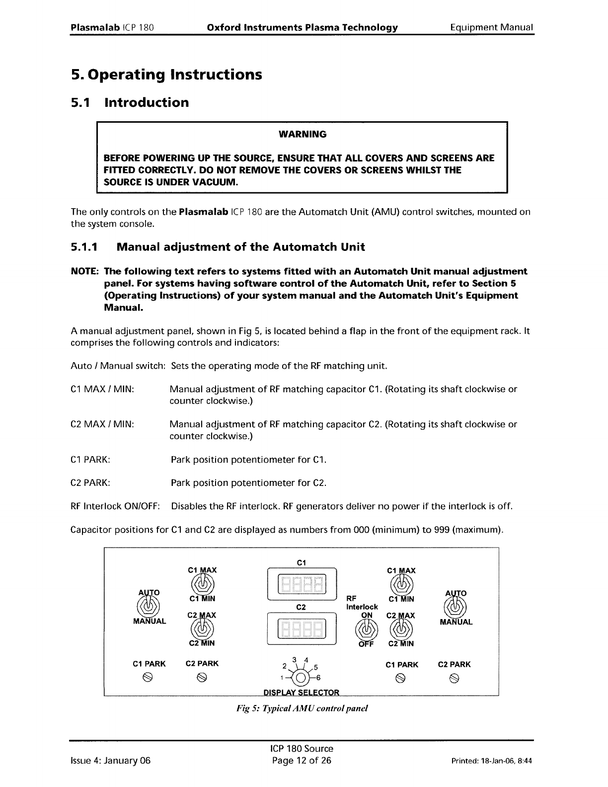
A manual
adjustment
panel, shown in Fig
5,
is
located
behind
a
flap
in
the
front
of
the
equipment
rack.
It
comprises
the
following
controls and indicators:
Auto
/
Manual
switch: Sets
the
operating
mode
of
the
RF
matching
unit.
C1
MAX
/ MIN:
Manual
adjustment
of
RF
matching
capacitor
C1.
(Rotating its
shaft
clockwise
or
counter
clockwise.)
C2
MAX
/ MIN:
Manual
adjustment
of
RF
matching
capacitor
C2.
(Rotating its
shaft
clockwise
or
counter
clockwise.)
C1
PARK:
Park
position
potentiometer
for
C1.
C2
PARK:
Park
position
potentiometer
for
C2.
RF
Interlock ON/OFF: Disables
the
RF
interlock.
RF
generators
deliver
no
power
if
the
interlock
is
off.
Capacitor positions
for
C1
and
C2
are displayed
as
numbers
from
000
(minimum)
to
999 (maximum).
fIJ
MANUAL
C1
PARK
@
C1
MAX
~
C~
~
C2 PARK
2&5
1\QJ6
C1
MAX
RF
~
Interlock
ON
Ii
~
C2
IN
C1
PARK
@
fIJ
MANUAL
C2 PARK
Issue
4:
January 06
Fig 5: Typical
AMU
control
panel
ICP
180 Source
Page 12
of
26
Printed: 18-Jan-06, 8:44