Oxford-100-Manual.pdf - 第162页
Plasmalab Oxford Instruments Plasma Technology System Manual 3.3.4 PECVD particles Please note that once particles have been noticed, all wafers should be examined under a strong light source at various angles of inciden…
System
Manual
Oxford
Instruments
Plasma Technology
Plasma
lab
Another
possible cause
of
non-uniformity
is
wafer
material - GaAs
is
less
conductive,
so
large GaAs wafers
show
more
non-uniformity,
which
can
be
counteracted
to
some degree by increasing
the
LF
frequency,
but
there
is
a
trade-off
with
matching
(i.e. reflected
power
is
generally
higher
at
higher
frequency). (To
adjust
the
frequency,
Press
the
Program
button
- adjust
the
Frequency - press
the
Program
button
again
to
run
at
the
new
frequency).
For
LF
power,
the
PC
should
be
setting
(and
the
generator
should be
controlling)
load
power
as
this
is
the
power
that
actually reaches
the
plasma. The
matching
is
often
quite
bad
for
LF,
but
this
doesn't
matter
too
much
as
the
LF
generator
increases its
power
output
to
compensate and
to
ensure
that
the
power
delivered
to
the
load (load
power)
is
always
as
requested.
However,
it
is
advisable
to
adjust
the
step-up
transformer
to
minimize
reflected power,
to
avoid
overheating
of
the
LF
generator,
especially
as
the
RFPP
generators
will
switch themselves
off
automatically
if
reflected
power
is
above 40-50W
for
self-protection.
3.3.3
Premature
flaking
of
chamber
wall
I
showerhead
material
Premature
flaking
of
chamber
wall/
showerhead
material
can occur
for
a
number
of
reasons:
1)
For
new
systems
the
showerhead may need several deposition/clean cycles
before
it
reaches its
best
film
adhesion performance. This can be
improved
by bead blasting
the
showerhead.
2)
Temperature
cycling
of
showerhead / chamber walls can cause
flaking,
therefore
it
is
important
that
chamber walls are set
to
a stable
temperature,
e.g.
60C,
and
that
the
showerhead
cooling
water
is
flowing
properly.
It
is
also
important
that
electrode
temperature
is
maintained
at
a
constant
value
as
this
will
also
affect
showerhead
temperature.
3)
The system should
not
be switched
off
overnight
to
save power. The system should be
left
pumping
with
electrode
maintained
at
deposition
temperature
at
all times
to
avoid
flaking.
4)
Incomplete
cleaning
during
a previous clean cycle can lead
to
premature
flaking.
5)
Wiping
of
chamber and
or
showerhead
with
water
or
IPA can leave residues
which
subsequently
causes early
flake-off
of
films deposited.
6)
Wiping
of
chamber walls / showerhead
with
clean
room
wipes
while
they
are
hot
can also leave
behind
residues
which
cause
premature
flaking.
7)
Repeated
venting
of
chamber
will
cause
flaking.
This one
of
the
main
reasons
that
for
a
PECVD
80
Plus
or
a
PECVD
800 Plus,
it
is
recommended
to
clean every 5-10 microns
of
film,
whereas
for
a
load locked
PECVD
System 100
running
high
rate
SiOz
films,
it
is
not
necessary
to
clean
as
often.
8)
Mixed
deposition
of
oxide,
nitride,
and
oxynitride
films can cause increased stresses in deposited
films and hence
premature
flaking.
9)
Changes
to
standard recipes can also cause increased stress and hence
premature
flaking.
For a
PECVD
System100
running
high
rate
oxide
we
recommend plasma cleaning every 100microns
for
best
film
repeatability.
A
dry
wipe
of
showerhead and vacuum cleaning
of
any large particles may also be
required.
For a
PECVD
80 Plus
or
PECVD
800 Plus,
it
is
recommended
to
clean every
5-1
Omicrons
of
film. Plasma
cleaning may need
to
be
carried
out
more
often
if
mixing
depositions
or
using a range
of
electrode
temperatures
etc
as
listed above. A
dry
wipe
of
showerhead and vacuum cleaning
of
any large particles
may also be required.
Process
Information
(Information
contained
in
this
document
is
confidential)
Printed: 08 January 2006 09:37 Page 19
of
30
Issue
1:
December 03
Plasmalab
Oxford
Instruments
Plasma
Technology
System Manual
3.3.4
PECVD
particles
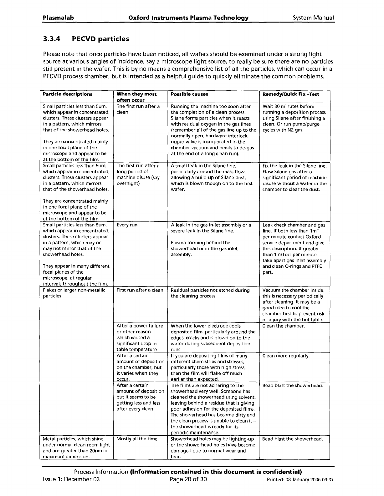
Please
note
that
once particles have been noticed, all wafers should be examined
under
a strong
light
source
at
various angles
of
incidence,
say
a microscope
light
source,
to
really be sure
there
are
no
particles
still present in
the
wafer. This
is
by
no
means a comprehensive list
of
all
the
particles,
which
can occur in a
PECVD
process chamber,
but
is
intended
as
a
helpful
gUide
to
quickly
eliminate
the
common problems.
Particle
descriptions
When
they
most
Possible causes Remedy/Quick Fix
-Test
often
occur
Small particles
less
than
Sum, The
first
run
after
a
Running
the
machine
too
soon
after
Wait
30
minutes
before
which
appear
in
concentrated, clean
the
completion
of
a clean process.
running
a
deposition
process
clusters. These clusters appear Silane forms particles
when
it
reacts using Silane
after
finishing a
in
a
pattern,
which
mirrors
with
residual oxygen
in
the
gas lines clean.
Or
run
pump/purge
that
of
the
showerhead holes.
(remember
all
of
the
gas line
up
to
the
cycles
with
N2
gas.
normally
open,
hardware
interlock
They are concentrated mainly
nupro
valve
is
incorporated
in
the
in
one focal plane
of
the
chamber vacuum and needs
to
de-gas
microscope
and
appear
to
be
at
the
end
of
a long clean run).
at
the
bottom
of
the
film.
Small particles
less
than
Sum,
The
first
run
after
a
A small leak
in
the
Silane line,
Fix
the
leak
in
the
Silane line.
which
appear
in
concentrated,
long
period
of
particularly
around
the
mass
flow,
Flow Silane gas
after
a
clusters. These clusters appear machine disuse
(say
allowing
a
build-up
of
Silane dust,
significant
period
of
machine
in a
pattern,
which
mirrors
overnight)
which
is
blown
though
on
to
the
first
disuse
without
a
wafer
in
the
that
of
the
showerhead holes.
wafer.
chamber
to
clear
the
dust.
They are concentrated
mainly
in
one focal plane
of
the
microscope and appear
to
be
at
the
bottom
of
the
film.
Small particles
less
than
Sum,
Every
run
A leak in
the
gas
in-let
assembly
or
a
Leak check chamber and gas
which
appear
in
concentrated, severe leak
in
the
Silane line.
line.
If
both
less
than
1mT
clusters. These clusters appear
per
minute
contact
Oxford
in a
pattern,
which
mayor
Plasma
forming
behind
the
service
department
and give
may
not
mirror
that
of
the
showerhead
or
in
the
gas
inlet
this
description.
If
greater
showerhead holes.
assembly.
than
1
mTorr
per
minute
take
apart
gas
inlet
assembly
They appear
in
many
different
and clean O-rings and
PTFE
focal planes
of
the
part.
microscope,
at
regular
intervals
throuqhout
the
film.
Flakes
or
larger
non-metallic
First
run
after
a clean Residual particles
not
etched
during
Vacuum
the
chamber inside,
particles
the
cleaning process
this
is
necessary periodically
after
cleaning.
It
may be a
good
idea
to
cool
the
chamber
first
to
prevent risk
of
iniurv
with
the
hot
table.
After
a
power
failure
When
the
lower
electrode cools Clean
the
chamber.
or
other
reason
deposited
film,
particularly
around
the
which
caused a
edges, cracks and
is
blown
on
to
the
significant
drop
in
wafer
during
subsequent
deposition
table
temperature
runs.
After
a certain
If
you
are
depositing
films
of
many
Clean
more
regularly.
amount
of
deposition
different
chemistries and stresses,
on
the
chamber,
but
particUlarly those
with
high
stress,
it
varies
when
they
then
the
film
will
flake
off
much
occur.
earlier
than
expected.
After
a certain
The films are
not
adhering
to
the
Bead blast
the
showerhead.
amount
of
deposition
showerhead very
well.
Someone has
but
it
seems
to
be cleaned
the
showerhead using solvent,
getting
less
and
less
leaving
behind
a residue
that
is
giving
after
every clean.
poor
adhesion
for
the
deposited films.
The showerhead has become
dirty
and
the
clean process
is
unable
to
clean
it
-
the
showerhead
is
ready
for
its
periodic maintenance.
Metal
particles,
which
shine
Mostly
all
the
time
Showerhead holes may be
lighting-up
Bead blast
the
showerhead.
under
normal clean
room
light
or
the
showerhead holes have become
and are
greater
than
20um in
damaged
due
to
normal
wear
and
maximum
dimension.
tear.
Process
Information
(Information
contained
in
this
document
is
confidential)
Issue
1:
December
03
Page
20
of
30
Printed: 08 January 2006 09:37
System
Manual
Oxford
Instruments
Plasma
Technology
Plasma
lab
Particle
descriptions
When
they
most
Possible
causes
Remedy/Quick
Fix
-Test
often
occur
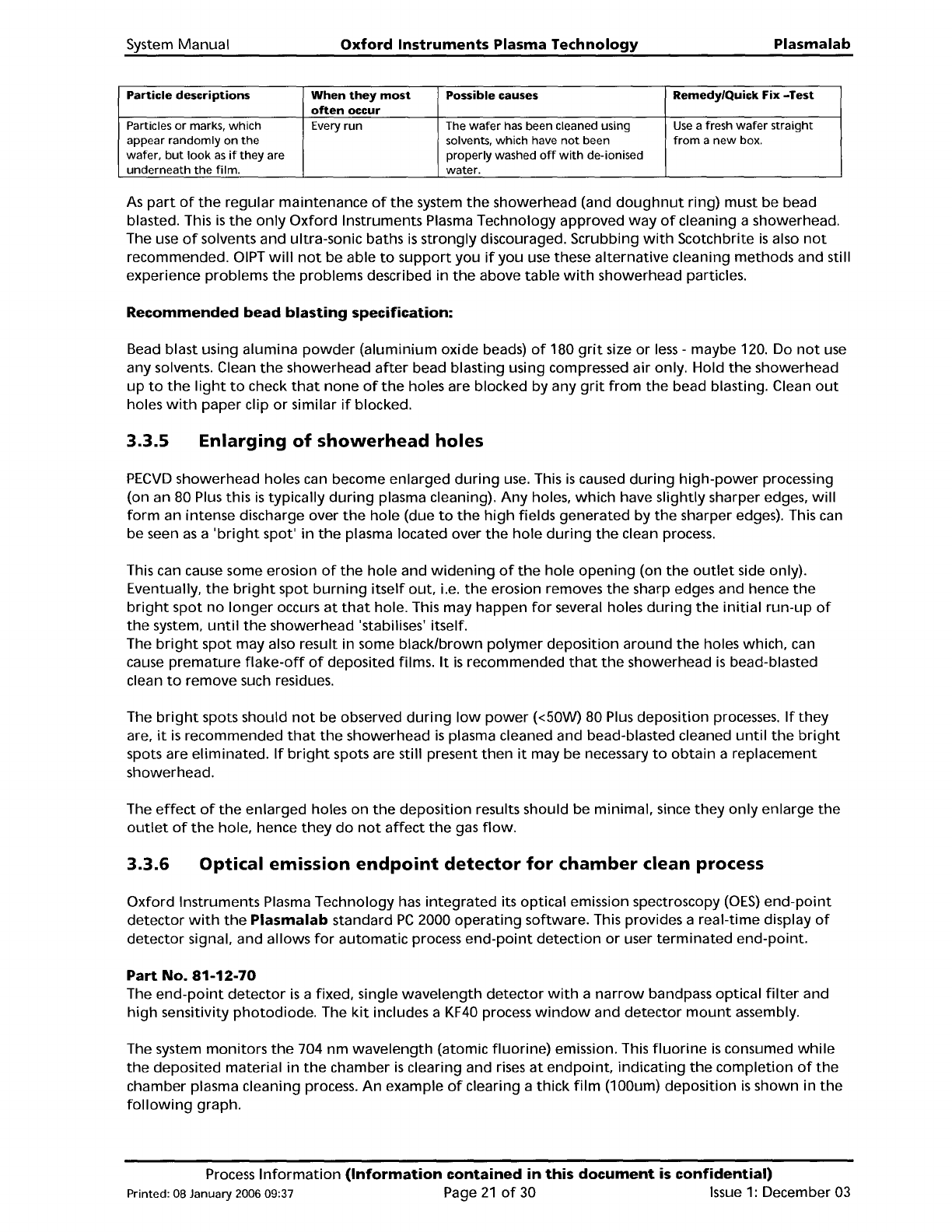
Particles
or
marks,
which
Every
run
The
wafer
has been cleaned using
Use
a fresh
wafer
straight
appear
randomly
on
the
solvents,
which
have
not
been
from
a
new
box.
wafer,
but
look
as
if
they
are
properly
washed
off
with
de-ionised
underneath
the
film.
water.
As
part
of
the
regular
maintenance
of
the
system
the
showerhead (and
doughnut
ring) must be bead
blasted. This
is
the
only
Oxford
Instruments Plasma Technology approved
way
of
cleaning a showerhead.
The use
of
solvents and ultra-sonic baths
is
strongly
discouraged. Scrubbing
with
Scotchbrite
is
also
not
recommended.
OIPT
will
not
be
able
to
support
you
if
you
use these
alternative
cleaning
methods
and still
experience problems
the
problems described in
the
above
table
with
showerhead particles.
Recommended
bead
blasting
specification:
Bead blast using alumina
powder
(aluminium
oxide beads)
of
180
grit
size
or
less
- maybe 120. Do
not
use
any solvents. Clean
the
showerhead
after
bead blasting using compressed air only. Hold
the
showerhead
up
to
the
light
to
check
that
none
of
the
holes are blocked by any
grit
from
the
bead blasting. Clean
out
holes
with
paper
clip
or
similar
if
blocked.
3.3.5
Enlarging
of
showerhead
holes
PECVD
showerhead holes can become
enlarged
during
use.
This
is
caused
during
high-power
processing
(on an 80 Plus this
is
typically
during
plasma cleaning).
Any
holes,
which
have
slightly
sharper edges,
will
form
an intense discharge over
the
hole
(due
to
the
high
fields
generated
by
the
sharper edges). This can
be seen
as
a
'bright
spot'
in
the
plasma located over
the
hole
during
the
clean process.
This can cause some erosion
of
the
hole
and
widening
of
the
hole
opening
(on
the
outlet
side only).
Eventually,
the
bright
spot
burning
itself
out,
i.e.
the
erosion removes
the
sharp edges and hence
the
bright
spot
no
longer
occurs
at
that
hole. This may happen
for
several holes
during
the
initial
run-up
of
the
system,
until
the
showerhead 'stabilises' itself.
The
bright
spot
may also result in some
black/brown
polymer
deposition
around
the
holes which, can
cause
premature
flake-off
of
deposited films.
It
is
recommended
that
the
showerhead
is
bead-blasted
clean
to
remove such residues.
The
bright
spots should
not
be observed
during
low
power
«50W)
80 Plus
deposition
processes.
If
they
are,
it
is
recommended
that
the
showerhead
is
plasma cleaned and bead-blasted cleaned
until
the
bright
spots are
eliminated.
If
bright
spots are still present
then
it
may be necessary
to
obtain
a replacement
showerhead.
The
effect
of
the
enlarged
holes on
the
deposition
results should be
minimal,
since
they
only
enlarge
the
outlet
of
the
hole, hence
they
do
not
affect
the
gas
flow.
3.3.6
Optical
emission
endpoint
detector
for
chamber
clean
process
Oxford
Instruments Plasma Technology has
integrated
its optical emission spectroscopy
(OES)
end-point
detector
with
the
Plasma
lab
standard
PC
2000
operating
software. This provides a real-time display
of
detector
signal, and allows
for
automatic
process
end-point
detection
or
user
terminated
end-point.
Part
No.
81-12-70
The
end-point
detector
is
a fixed, single
wavelength
detector
with
a
narrow
bandpass optical
filter
and
high
sensitivity
photodiode.
The
kit
includes a
KF40
process
window
and
detector
mount
assembly.
The system
monitors
the
704
nm
wavelength
(atomic
fluorine)
emission. This
fluorine
is
consumed
while
the
deposited
material
in
the
chamber
is
clearing and
rises
at
endpoint,
indicating
the
completion
of
the
chamber plasma cleaning process.
An
example
of
clearing a
thick
film
(100um)
deposition
is
shown in
the
following
graph.
Process
Information
(Information
contained
in
this
document
is
confidential)
Printed: 08 January 2006 09:37 Page
21
of
30
Issue
1:
December 03