Oxford-100-Manual.pdf - 第226页
OIPT Systems Oxford Instruments Plasma Technology System Manual 2.2.1 Mandatory Specifications for total loss cooling systems CAUTION If clear (i.e. transparent) tUbing is exposed to sunlight, algal growth can develop, w…
System
Manual
Oxford
Instruments
Plasma
Technology
OIPT
Systems
Pressure:
Adjustable
0.7
to
4.2
bar
(10
to
60
psi).
Chiller
I
heat
exchanger
to
be
fitted
with
a
bypass
having
a
capacity
of
100%
of
rated
flow.
Temperature
range:
See
system
installation
data
sheets.
Minimum
flows:
See
system
installation
data
sheets.
Cooling
capacity:
See
system
installation
data
sheets.
Coolant:
Hexid
A40
(OIPT
Part
No.
GIWATERISUN/007
for
15
litres)2.
This
product
is
propylene
glycol
based,
and
is
pre-diluted
ready
for
use.
See
sub-section
2.1
for
the
warranty
impact
of
not
using
this
product.
Filtration:
10
micron
metal
mesh
water
filter.
Maximum
pressure
drop
0.15
bar
(2.2
psi)
at
rated
flow.
For
example,
filter
element
Balston
SMC-100-12-10.
2.2
Total
Loss
Cooling
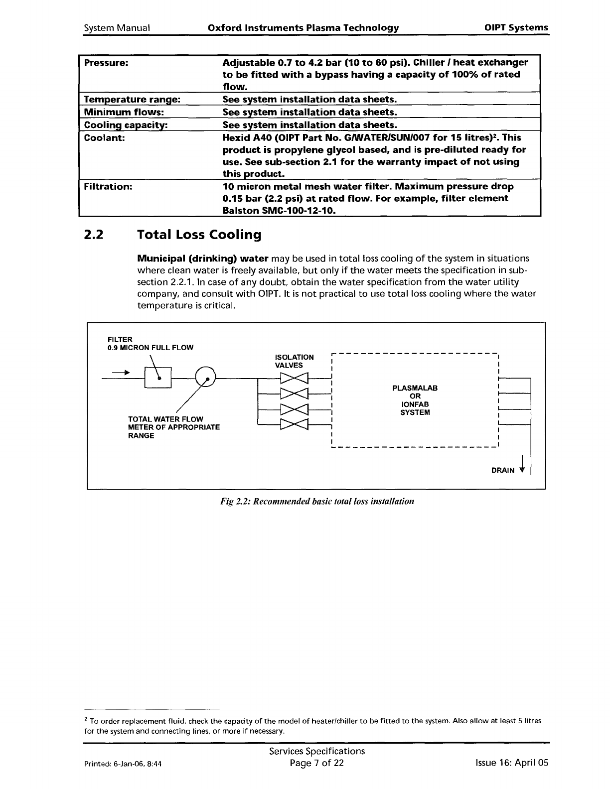
Municipal
(drinking)
water
may be used
in
total
loss
cooling
of
the
system
in
situations
where
clean
water
is
freely available.
but
only
if
the
water
meets
the
specification in sub-
section
2.2.1. In
case
of
any
doubt.
obtain
the
water
specification
from
the
water
utility
company. and consult
with
DIPT.
It
is
not
practical
to
use
total
loss
cooling
where
the
water
temperature
is
critical.
FILTER
0.9
MICRON FULL FLOW
TOTAL WATER FLOW
METER OF APPROPRIATE
RANGE
ISOLATION
VALVES
~
--- - ---- ---- - ---- - --
--,
I '
I
PLASMALAB
OR
10NFAB
SYSTEM
DRAIN
~
Fig 2.2: Recommendedbasic total loss installation
2
To
order
replacement
fluid,
check
the
capacity
of
the
model
of
heater/chiller
to
be
fitted
to
the
system. Also
allow
at
least 5 Iitres
for
the
system and connecting lines,
or
more
if
necessary.
Printed: 6-Jan-06, 8:44
Services Specifications
Page 7
of
22
Issue
16:
April
05
OIPT Systems
Oxford
Instruments
Plasma
Technology
System
Manual
2.2.1
Mandatory
Specifications
for
total
loss
cooling systems
CAUTION
If
clear
(i.e.
transparent)
tUbing
is
exposed
to
sunlight,
algal
growth
can
develop,
which
can
restrict
coolant
flow.
It
is
MANDATORY
that
clear
tUbing
is
not
used
in
any
part
of
the
cooling
system.
OIPT
recommends
the
use
of
either
black
or
dark
green
tubing.
CAUTION
It
is
the
customer's
responsibility
not
to
exceed
a pressure
of
5
bar,
or
other
limit
that
has
been
set
for
the
system.
Exceeding
this
safe
pressure
may
cause
irreparable
damage
to
system
components.
If
total
loss
cooling
with
municipal
water
(drinking
quality
water)
is
used in
the
system
or
in
the
pumps,
the
water
quality
must
meet
the
following
specifications.
Note
that
increased
maintenance
will
be
required
if
this
water
is
used directly
in
the
system
as
well
as
in
the
pumps.
The
water
must be
kept
warm
enough
to
prevent
condensation
on
chamber surfaces and
outside system components. This applies
to
those parts
of
the
system inside
the
clean
room
and those parts in a service area. Condensation can
damage
components such
as
RF
power
supplies,
ferrofluidic
seals and
automatch
units.
Any
damage
so
caused
cannot
be covered by
the
system
warranty.
•
Pressure:
4
to
5
bar.
Backpressure
from
the
drain
must
be
less
than
1
bar.
•
Temperature:
10°C
to
25°C
• pH:
7
to
8
•
Oxy~en:
Greater
than
4m~/litre
•
CO
2
and
NH
3
:
Less
than
10mg/litre
•
Chloride:
Less
than
100mg/litre
•
Calcium
Less
than
75mg/litre
Carbonate:
•
Filtration:
To
0.9
micron
full
flow,
for
example
filter
element
Balston
200-50-50
or
200-95-50.
Issue
16:
April
05
Services Specifications
Page 8
of
22
Printed: 6-Jan-06, 8:44
System
Manual
Oxford
Instruments
Plasma
Technology
OIPT Systems
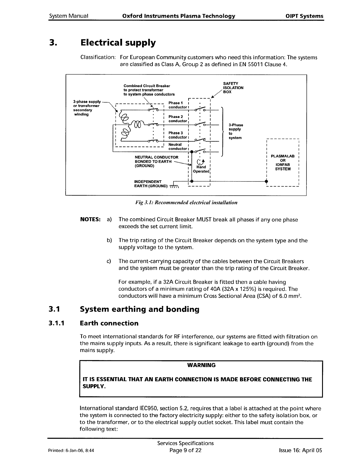
3. Electrical
supply
Classification: For European
Community
customers
who
need this
information:
The systems
are classified
as
Class
A,
Group
2
as
defined
in
EN
55011
Clause
4.
PLASMALAB
OR
10NFAB
SYSTEM
3-Phase
supply
to
system
NEUTRAL CONDUCTOR
BONDED TO EARTH
(GROUND)
I
-------------
SAFETY
Combined
Circuit
Breaker ISOLATION
to
protect
transformer
/ BOX
to
system
phase
conductors
¥
~
r-----I
3-phase
supply
~
_ _ _ _ _ _ _ _ _ _ _ Phase 1 1 • I
or
transformer
1 • I
conductor
1 • I
secondary I : C>--j--
winding
I • I 1 1
I 1 Phase 2 I
I • 1
conductor
I 1
'---o,....,....,I:l-r----i--<;r-:-.
o-f-
Phase 3 : 1
conductor
I
~
:
Neutral I
.--:--
conductor
1 I
'--------------,-e-o--=-C>--j--
I
(jl
Hand :
Operated1
1
INDEPENDENT
EARTH (GROUND)
______
1
Fig 3.1: Recommended electrical installation
NOTES:
a)
The
combined
Circuit Breaker MUST break all phases
if
anyone
phase
exceeds
the
set
current
limit.
b) The
trip
rating
of
the
Circuit Breaker depends
on
the
system
type
and
the
supply
voltage
to
the
system.
c)
The current-carrying capacity
of
the
cables
between
the
Circuit Breakers
and
the
system must be
greater
than
the
trip
rating
of
the
Circuit Breaker.
For example,
if
a 32A Circuit Breaker
is
fitted
then
a cable having
conductors
of
a
minimum
rating
of
40A (32A x 125%)
is
required. The
conductors
will
have a
minimum
Cross
Sectional Area
(CSA)
of
6.0
mm
2
•
3.1
System
earthing
and
bonding
3.1.1
Earth
connection
To
meet
international
standards
for
RF
interference,
our
systems are
fitted
with
filtration
on
the
mains supply inputs.
As
a result,
there
is
significant
leakage
to
earth
(ground)
from
the
mains supply.
WARNING
IT IS ESSENTIAL THAT
AN
EARTH CONNECTION IS
MADE
BEFORE
CONNECTING THE
SUPPLY.
International
standard IEC950, section 5.2, requires
that
a label
is
attached
at
the
point
where
the
system
is
connected
to
the
factory
electricity supply:
either
to
the
safety isolation box,
or
to
the
transformer,
or
to
the
electrical supply
outlet
socket. This label must contain
the
following
text:
Printed: 6-Jan-06, 8:44
Services Specifications
Page 9
of
22
Issue
16:
April
05