Oxford-100-Manual.pdf - 第281页
System Manual Oxford Instruments Plasma Technology All OIPT Systems 6. Troubleshooting WARNING HAZARDOUS RF VOLTAGE - CONTACT CAN CAUSE DEATH, SEVERE INJURY OR BURNS. ANY WORK REQUIRING THE REMOVAL OF COVERS OR PANELS MU…
All
OIPT Systems
Oxford
Instruments
Plasma
Technology
System
Manual
Auto/manual
switch: In
the
'Auto'
position,
the
unit
will
attempt
to
tune
for
minimum
reflected
RF
power. In
the
'Manual'
position,
the
capacitors
positions are
controlled
manually.
C1
max/min switch: In manual mode, this switch can be used
to
drive
capacitor
C1
towards
maximum
or
minimum.
C2
max/min switch: In manual mode, this switch can be used
to
drive
capacitor
C2
towards
maximum
or
minimum.
Note
that
capacitor positions are displayed
as
a
three-digit
number
from
000 (minimum)
to
999 (maximum).
Display Selector
Switch:
C1
park.
Potentiometer:
C2
park.
Potentiometer:
The
RF
monitoring
positions display
the
analogue
voltages
on
the
remote
control
lines
to
the
RF
generators,
as
a service aid. The
Hillo
position reads a
high
(>9V) value
when
the
wafer
bias
RF
supply
is
at
full
scale, and a
low
«1V)
value
when
this supply
is
scaled back
to
one-
tenth
full
power. This
feature
improves resolution
of
RF
low
power.
This
control
can be
fitted
either
to
the
control
panel
or
on
the
AMU
control
board. The
automatch
will
drive
C1
to
this pre-set position
when
the
RF
is
turned
off,
if
the
unit
is
set
to
'auto'
This
control
can be
fitted
either
to
the
control
panel
or
on
the
AMU
control
board. The
automatch
will
drive
C2
to
this pre-set
position
when
the
RF
is
turned
off,
if
the
unit
is
set
to
'auto'
Issue
6:
February
05
DIPT
Automatch
Unit
Page 14
of
20
Printed: 5-Jan-06. 8:03
System
Manual
Oxford
Instruments
Plasma Technology
All OIPT Systems
6.
Troubleshooting
WARNING
HAZARDOUS
RF
VOLTAGE - CONTACT CAN CAUSE DEATH,
SEVERE
INJURY
OR
BURNS.
ANY
WORK REQUIRING
THE
REMOVAL
OF
COVERS
OR
PANELS MUST
ONLY
BE
PERFORMED
BY
AUTHORISED PERSONNEL WHO
ARE
AWARE
OF
THE
HAZARDS INVOLVED.
6.1
Fault
diagnosis
chart
Use
the
following
chart
to
locate
and
identify
faults.
Note
that
the
chart
lists typical
fault
symptoms
and
is
not
exhaustive.
SYMPTOM
POSSIBLE CAUSES ACTION
(A)
Drive
motors
do
Fuse
FS2
blown
Investigate
and
repair
fault,
which
caused
the
not
respond
to
fuse
to
blow.
Then
renew
the
fuse.
automatic
or
manual
control
Fuse
FS1
or
FS101
tripped.
Investigate
and
repair
the
fault,
which
caused
the
fuse
to
trip.
(The fuses
will
automatically
reset once
the
fault
is
repaired.)
Note
that
these
components
are
semiconductor
fuses
which
respond
to
an increase in
current
above
their
rating
(approximately
200 mA)
by
increasing
their
internal
resistance significantly.
The
voltage
drop
across each
of
these
components
under
non-fault
conditions
is
approximately
0.5V
When
tripped
by
high
current,
the
voltage
drop
is
almost
the
full
supply
voltage
i.e. 24V.
After
power
is
removed,
the
devices
require
20
seconds
to
cool
down
and
reset.
(8)
C1
or
C2
drive
to
1.
C1
or
C2
starting
too
far
Adjust
park
potentiometers
(Refer
to
sub-
min
or
max
from
final
match
position
section 6.4 (paqe 20).
2.
Match
position
is
out
of
1.
Change process
conditions
accessible
range
2.
Change
component
fit
in
AMU
(skilled
personnel only). Refer
to
sub-section 6.3 (page
19).
(C)
C1
or
C2
drive
to
Capacitor
has
travelled
past
1.
All
vane capacitors
only:
Continue
manual
min
or
max
and
do
an electrical
limit
travel
in
the
same
direction
(to
max
if
capacitor
not
return
is
at
max). The
capacitor
will
turn
fully
until
it
manually
passes
the
opposite
limit.
2.
Readiust
limit
settinqs
(D)
Plasma does
not
Gas
pressure
is
too
low
or
Caution:
do
not
run
for>
2
minutes
in
this
strike
even
though
too
high
condition.
Change gas pressure
to
20 - 200
the
reflected
power
mTorr
range
(RIE),
or
0.5
-1.5
Torr
range
is
low
(PECVD)
Printed: 5-Jan-06. 8:03
DIPT
Automatch
Unit
Page 15
of
20
Issue
6:
February 05
All
OIPT Systems
Oxford
Instruments
Plasma
Technology
System
Manual
SYMPTOM
POSSIBLE CAUSES ACTION
(E)
C1
or
C2
oscillate
1.
Amplifier
gain
too
high
See
sub-section 6.1.1 (page 16).
close
to
match
2.
C1
or
C2
spindle
thread
Remove capacitor, clean and re-Iubricate
dirty.
capacitor's spindle
thread
and bearing.
Re-
aliqn;
see
sub-section 6.1.2 (paqe 17).
(F)
Drive
motor
shafts
Coupling
between
the
motor
See
sub-section 6.1.2 (page 17).
rotate
but
capacitor shafts and capacitor spindles
spindles
do
not.
has become disengaged
or
loose.
(G)
End stops
don't
Park
potentiometers
have
Check park
potentiometers
behind
AMU
work,
motor
drives
broken
control
panel and replace
if
necessary.
throuqh.
(H)
Error signal pots
Links placed incorrectly Check links
LK6,
7,
10 & 107
to
ensure
they
are
don't
adjust
the
in
the
correct position.
If
link
is
open
end type,
error
signal
or
both
ensure
that
metal
insert
is
still present.
adjust
one
signal
only.
Hints
and
Tips
• Do
not
remove
anything
from
the
Motor
Control
board
without
removing
the
power
(JP2)
first.
•
When
in
'Auto'
mode
RV1
and
RV2
found
on
the
side
of
the
AMU
casing can be used
to
make
fine
adjustments
to
the
match position.
6.1.1
Amplifier
gain
adjustment
Refer
to
Symptom
(E)
in
the
Fault diagnosis
chart
(see
sub-section 6.1, page 15).
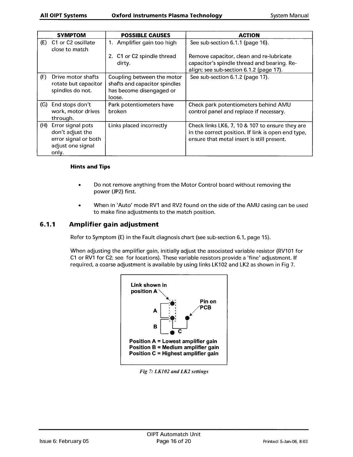
When
adjusting
the
amplifier
gain,
initially
adjust
the
associated variable resistor
(RV101
for
C1
or
RV1
for
C2;
see
for
locations). These variable resistors
provide
a
'fine'
adjustment.
If
required, a coarse
adjustment
is
available by using links LK102 and
LK2
as
shown in Fig
7.
Link shown
in
PositionA~
; -
~
Pin on
[
:e:
/PCB
A
::
[
:e:
e
B
-LJ
e
C
Position A = Lowest amplifier gain
Position B
= Medium amplifier gain
Position C
= Highest amplifier gain
Fig
7:
LKI02
and
LK2 settings
Issue
6:
February 05
DIPT
Automatch
Unit
Page 16
of
20 Printed: 5-Jan-06, 8:03