Oxford-100-Manual.pdf - 第140页
PlasmalabSystem 100 Oxford Instruments Plasma Technology WARNING System Manual BEFORE PROCEEDING WITH ANY MAINTENANCE WORK, READ SECTION 1 - HEALTH AND SAFETY. 6.14 Automatic load lock end effector adjustments for differ…
System
Manual
Oxford
Instruments
Plasma Technology
WARNING
PlasmalabSystem
100
BEFORE
PROCEEDING WITH
ANY
MAINTENANCE WORK, READ SECTION 1 - HEALTH
AND
SAFETY.
6.13
Adjusting
the
lower
electrode
wafer
clamp
clamping
force
To adjust
the
clamping
force, use
the
following
procedure
(refer
to
Fig
6.1
and Fig 6.2):
11) Open
the
process chamber lid.
12)
Wearing
powder-free
gloves, unscrew
the
three
clamping
plate
securing screws
then
remove
the
clamping
plate
from
the
process chamber and place
it
on a clean surface.
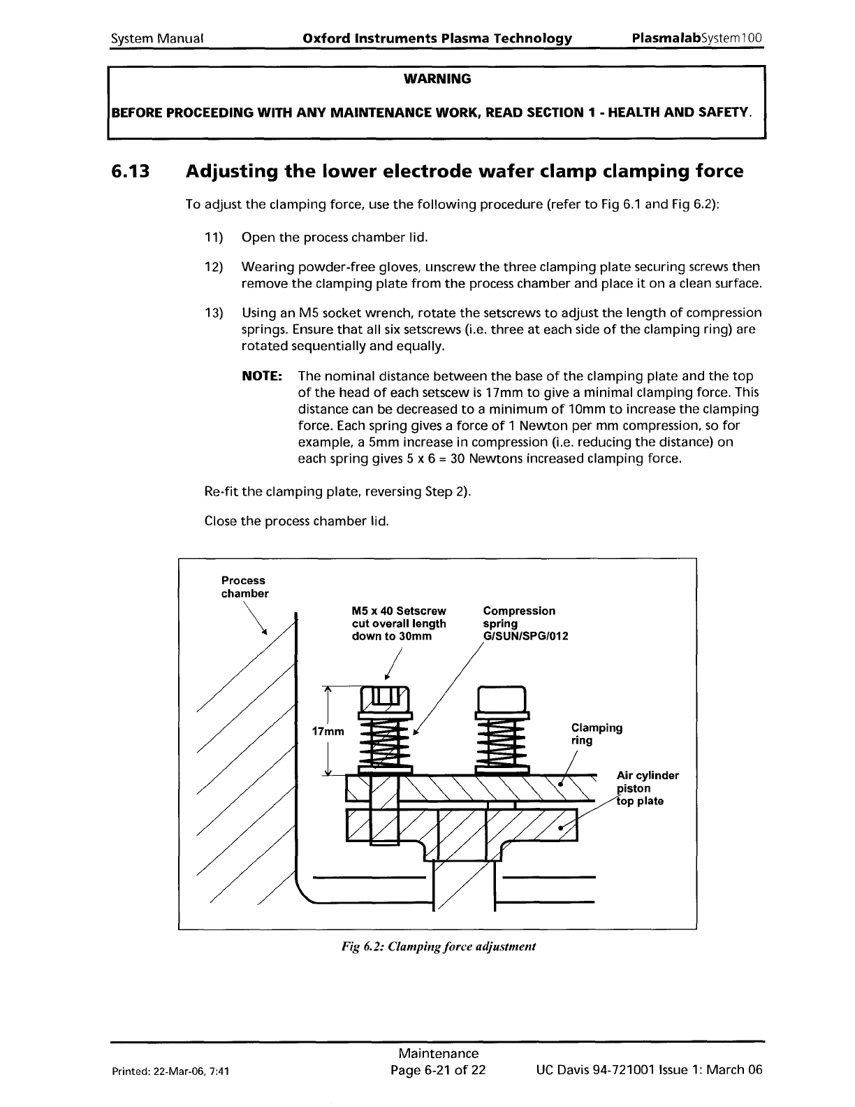
13) Using an
M5
socket wrench,
rotate
the
setscrews
to
adjust
the
length
of
compression
springs. Ensure
that
all six setscrews (i.e.
three
at
each side
of
the
clamping ring) are
rotated
sequentially
and
equally.
NOTE: The
nominal
distance
between
the
base
of
the
clamping
plate
and
the
top
of
the
head
of
each setscew
is
17mm
to
give a
minimal
clamping force. This
distance can be decreased
to
a
minimum
of
10mm
to
increase
the
clamping
force. Each spring gives a force
of
1
Newton
per mm compression.
so
for
example. a 5mm increase
in
compression (i.e. reducing
the
distance)
on
each spring gives 5 x 6 = 30 Newtons increased clamping force.
Re-fit
the
clamping
plate. reversing Step
2).
Close
the
process chamber lid.
Process
chamber
\
M5 x 40 Setscrew
cut overall length
down to 30mm
I
Compression
spring
G/SUN/SPG/012
Clamping
ring
Air cylinder
piston
top plate
Fig 6.2: Clampingforce adjustment
Printed: 22-Mar-06,
7:41
Maintenance
Page 6-21
of
22
UC
Davis 94-721001
Issue
1:
March 06
PlasmalabSystem100
Oxford
Instruments Plasma Technology
WARNING
System
Manual
BEFORE
PROCEEDING WITH
ANY
MAINTENANCE WORK, READ SECTION 1 - HEALTH
AND
SAFETY.
6.14
Automatic
load
lock
end
effector
adjustments
for
different
wafer
sizes
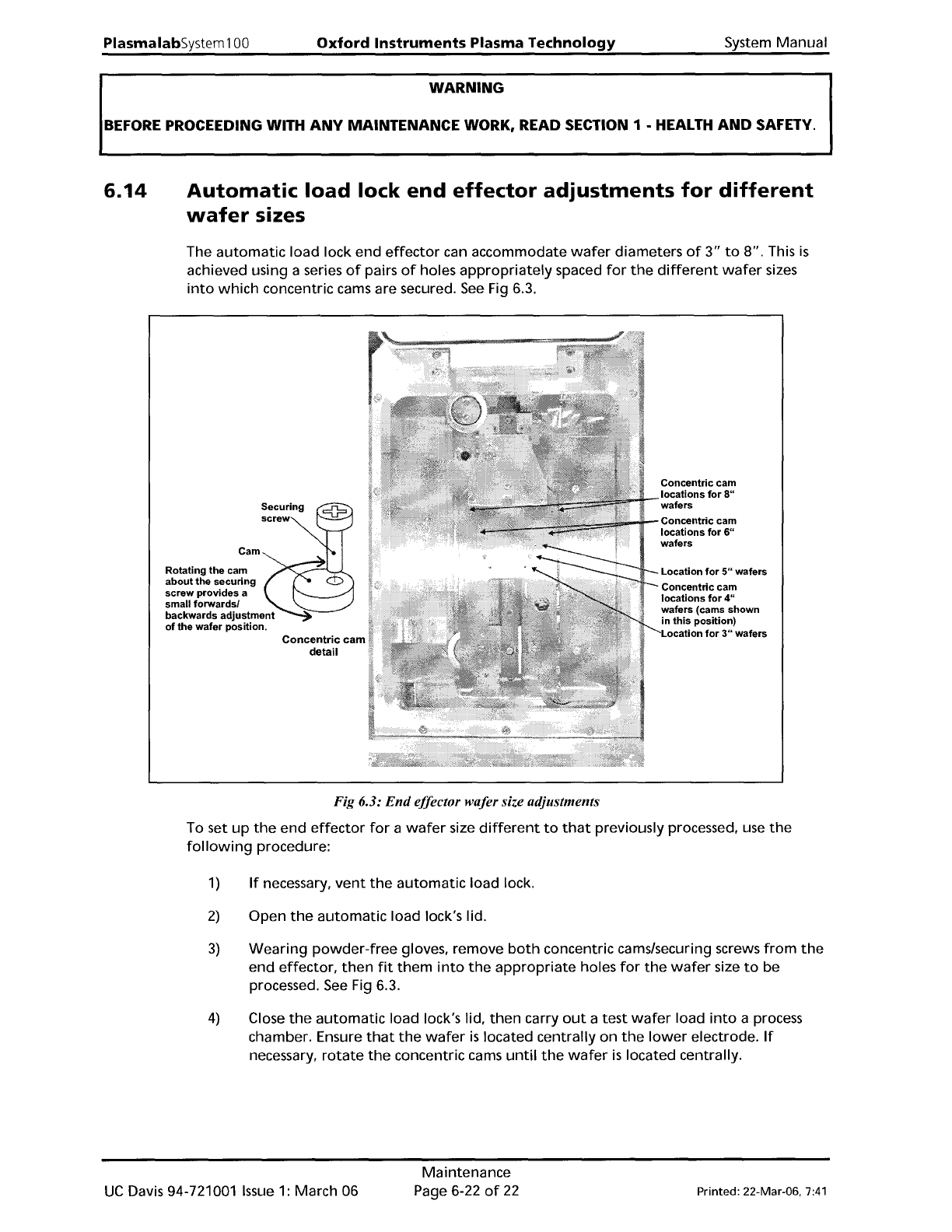
The
automatic
load
lock end
effector
can accommodate
wafer
diameters
of
3"
to
8".
This
is
achieved using a series
of
pairs
of
holes
appropriately
spaced
for
the
different
wafer
sizes
into
which
concentric cams are secured.
See
Fig 6.3.
Cam
Rotating
the
cam
about
the
securing
screw
provides
a
small
forwardsl
backwards
adjustment
of
the
wafer
position.
Concentric
cam
detail
Concentric
cam
locations
for
8"
wafers
Concentric
cam
locations
for
6"
wafers
Location
for
5"
wafers
Concentric
cam
locations
for
4"
wafers (cams
shown
in
this
position)
Location
for
3"
wafers
Fig 6.3:
End
effector wafer size adjustments
To set
up
the
end
effector
for
a
wafer
size
different
to
that
previously processed, use
the
following
procedure:
1)
If
necessary,
vent
the
automatic
load lock.
2)
Open
the
automatic
load lock's lid.
3)
Wearing
powder-free
gloves, remove
both
concentric cams/securing screws
from
the
end
effector,
then
fit
them
into
the
appropriate
holes
for
the
wafer
size
to
be
processed.
See
Fig 6.3.
4)
Close
the
automatic
load lock's lid,
then
carry
out
a test
wafer
load
into
a process
chamber. Ensure
that
the
wafer
is
located centrally
on
the
lower
electrode.
If
necessary,
rotate
the
concentric cams
until
the
wafer
is
located centrally.
UC
Davis 94-721001
Issue
1:
March 06
Maintenance
Page 6-22
of
22
Printed: 22-Mar-06.
7:41
System
Manual
Oxford
Instruments
Plasma Technology
Plasma
lab
System
100
7. Process
guide
& glossary
Printed:
25
May
200510:16
Process Guide and Glossary
Page
7-1
of
2
Issue
1:
December 03