Oxford-100-Manual.pdf - 第212页
PlasmalabSystem 100 Oxford Instruments Plasma Technology Installation Data 6. Pump set information CAUTION Where the rotary vane or Roots pumps are powered from a mains supply separate from the PiasmaiabSystem1 00, a sep…
Installation Data
Oxford
Instruments
Plasma
Technology
PiasmaiabSystem100
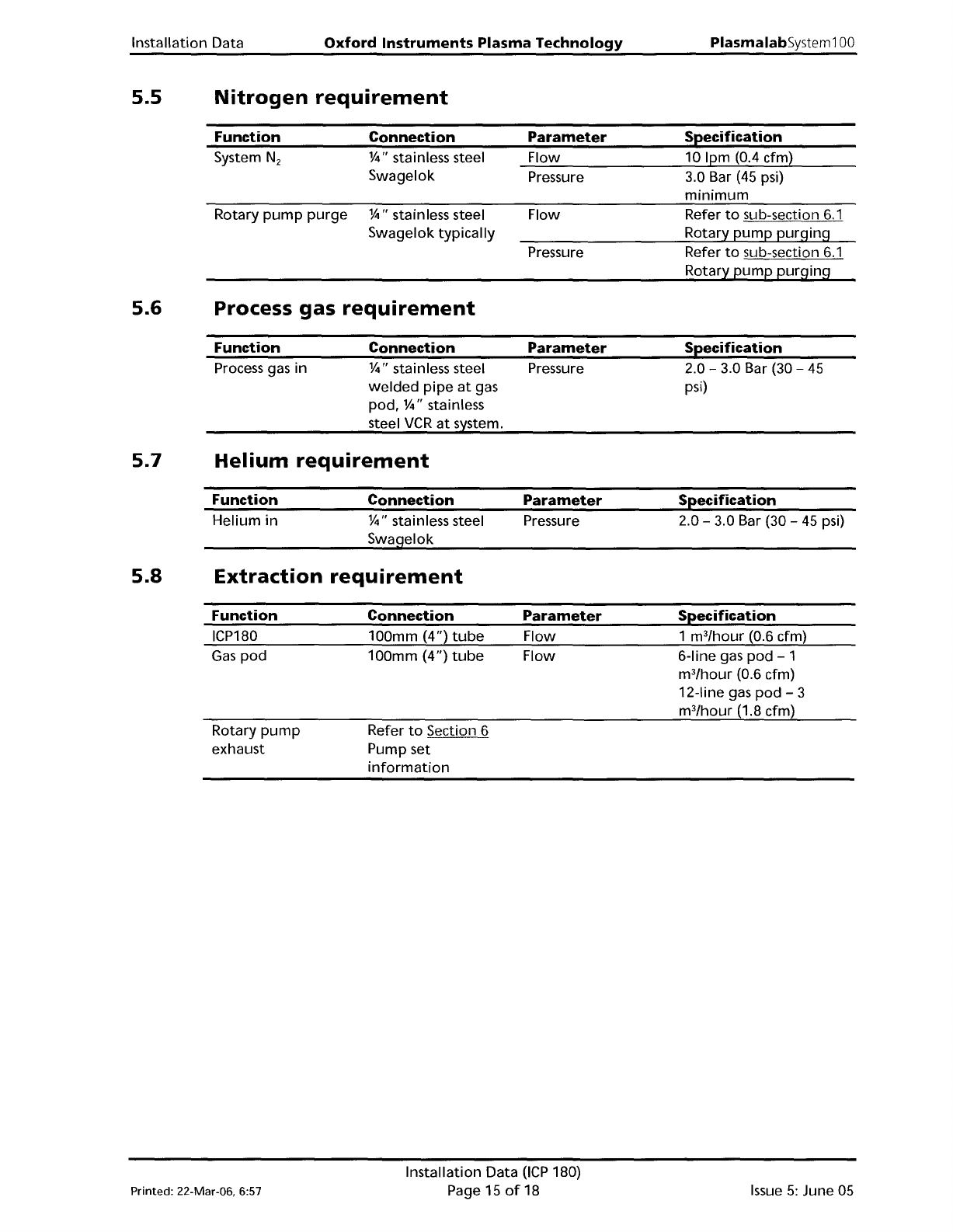
5.5
Nitrogen
requirement
Function
System N
2
Rotary
pump
purge
Connection
%"
stainless steel
Swagelok
%"
stainless steel
Swagelok
typically
Parameter
Flow
Pressure
Flow
Pressure
Specification
10 Ipm (0.4 cfm)
3.0 Bar
(45
psi)
minimum
Refer
to
sub-section
6.1
Rotary
pump
purging
Refer
to
sub-section
6.1
Rotary
pump
purging
5.6 Process gas
requirement
Function
Process gas in
Connection
%"
stainless steel
welded
pipe
at
gas
pod.
%"
stainless
steel
VCR
at
system.
Parameter
Pressure
Specification
2.0 - 3.0 Bar (30 -
45
psi)
5.7
Helium
requirement
Function
Helium
in
Connection
%"
stainless steel
Swagelok
Parameter
Pressure
Specification
2.0 - 3.0 Bar (30 -
45
psi)
5.8
Extraction
requirement
Function
ICP180
Gas
pod
Rotary
pump
exhaust
Connection
100mm (4")
tube
100mm
(4")
tube
Refer
to
Section 6
Pump set
information
Parameter
Flow
Flow
Specification
1 m
3
/hour
(0.6 cfm)
6-line gas
pod
- 1
m
3
/hour
(0.6 cfm)
12-line gas
pod
- 3
m
3
/hour
(1.8 cfm)
Printed: 22-Mar-06, 6:57
Installation Data
OCP
180)
Page
15
of
18
Issue
5:
June 05
PlasmalabSystem100
Oxford
Instruments
Plasma Technology
Installation Data
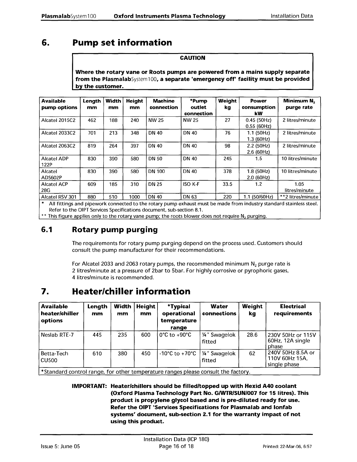
6.
Pump
set
information
CAUTION
Where
the
rotary
vane
or
Roots
pumps
are
powered
from
a
mains
supply
separate
from
the
PiasmaiabSystem1 00, a
separate
'emergency
off'
facility
must
be
provided
by
the
customer.
Available
Length
Width
Height
Machine
*Pump
Weight
Power
MinimumN
z
pump
options
mm mm
mm
connection
outlet
kg
consumption
purge
rate
connection
kW
Alcatel 2015C2
462 188 240
NW25
NW25
27
0.45 (50Hz)
2 litres/minute
0.55 (60Hz)
Alcatel 2033C2
701
213 348
ON
40
ON
40 76
1.1
(50Hz) 2 litres/minute
1.3 (60Hz)
Alcatel 2063C2
819 264 397
ON
40
ON
40
98
2.2 (50Hz) 2 litres/minute
2.6 (60Hz)
Alcatel
AOP
830 390 580
ON
50
ON
40 245 1.5
10
Iitreslminute
122P
Alcatel
830 390 580
ON
100
ON
40 378 1.8 (50Hz) 10 Iitres/minute
AOS602P
2.0 (60Hz)
Alcatel
ACP
609 185 310
ON
25
ISO
K-F
33.5 1.2 1.05
28G
Iitres/minute
Alcatel
RSV
301
880 510 1000
ON
40
ON
63
220 1.1 (50/60Hz) *
*2
litres/minute
*
All
fittings
and
pipework
connected
to
the
rotary
pump
exhaust
must
be made
from
industry standard stainless steel.
Refer
to
the
OIPT
Services Specifications document, sub-section 8.1.
** This
fiqure
applies
only
to
the
rotary
vane pump;
the
roots
blower
does
not
require
N?
purqinq.
6.1
Rotary
pump
purging
The requirements
for
rotary
pump
purging
depend on
the
process used. Customers should
consult
the
pump
manufacturer
for
their
recommendations.
For Alcatel 2033 and 2063
rotary
pumps,
the
recommended
minimum
N
z
purge
rate
is
2
litres/minute
at
a pressure
of
2bar
to
5bar. For
highly
corrosive
or
pyrophoric
gases,
4
litres/minute
is
recommended.
7.
Heater/chiller
information
Available
Length
Width
Height
*Typical
Water
Weight
Electrical
heater/chiller
mm mm mm
operational
connections
kg
requirements
options
temperature
range
Neslab
RTE-7
445
235 600
O°C
to
+90°C
%"
Swagelok 28.6
230V 50Hz
or
115V
fitted
60Hz, 12A single
phase
Betta-Tech
610 380
450 -10°C
to
+70°C
%"
Swagelok 62
240V 50Hz 8.5A
or
CU500
fitted
110V 60Hz 15A,
sinqle phase
*Standard
control
ranqe,
for
other
temperature
ranqes please consult
the
factory.
IMPORTANT: Heater/chillers should
be
filled/topped
up
with
Hexid
A40
coolant
(Oxford
Plasma
Technology
Part
No.
GIWTRlSUN/007
for
15
litres). This
product
is
propylene
glycol based
and
is
pre-diluted
ready
for
use.
Refer
the
OIPT 'Services Specifications
for
Plasmalab
and
lonfab
systems'
document,
sub-section 2.1
for
the
warranty
impact
of
not
using
this
product.
Issue
5:
June
05
Installation Data
(ICP
180)
Page 16
of
18
Printed: 22-Mar·06, 6:57
Installation Data
Oxford
Instruments
Plasma
Technology
PlasmalabSystem100
8.
Interlocks
There are
two
types
of
interlocks used
on
the
PlasmalabSystem100;
hardware
and software.
In all areas,
the
hardware
interlock
will
override
any
software
interlock. The
hardware
interlocks, and
their
effect
on
the
system components in
the
case
of
an
interlock
becoming
open
circuit
are
as
follows:
The electrical interlocks are
divided
into
two
circuits
controlling
the
power
to
the
system.
1)
The mains
power
connection
is
made
to
a system Power
Distribution
Unit. The Power
Distribution
Unit
will
disable all
of
its
power
outputs
under
the
following
conditions:
a)
If
the
Emergency
Off
button
is
pressed.
b)
Ifthere
is
an
interruption
of
the
power
input
to
the
system.
c)
If
the
Power
Distribution
Unit
external
facility
interlock
sensor
link
becomes
open
circuit.
NOTE:
The Power
Distribution
Unit
external
facility
interlock
sensor
link
enables
the
interlocks
of
external sensors, e.g. gas
detectors, exhaust scrubbers, etc.,
to
be
monitored
by
the
Power
Distribution
Unit. External
interlock
contacts connected
to
this
link
should be
voltage
free
and Normally Closed, i.e.
faulting
to
an Open Circuit.
2)
The system
internal
24V supply, comprises a process line and a chamber line:
The 24V process line,
which
controls
the
process gases and plasma
power
supply
units,
will
be
disabled
under
the
following
conditions:
a)
If
the
Vacuum Safety Switch
is
open circuit, i.e. Chamber Pressure> 600
mbar.
b)
If
the
load lock slitvalve
is
OPEN.
The 24V chamber
line
will
be disabled
under
the
following
conditions, leaving
the
system
controller
operational,
but
disabling all system components:
a)
If
the
Water
Flow
switch
is
not
closed.
b)
If
the
Chamber
top
is
OPEN.
Printed: 22·Mar·06, 6:57
Installation Data
(lCP
180)
Page 17
of
18
Issue
5:
June 05