2OM-1011-002.pdf - 第100页
0305-001 Tg0858-PM-PM (2) Example of Data Creation • Use placement data (P) U01 and placement data (O) U01. • Do not enter any parameters in placement data (V) because it is not used. • P .E.C. recognition must be specif…
0305-001 Tg0858-PM-PM
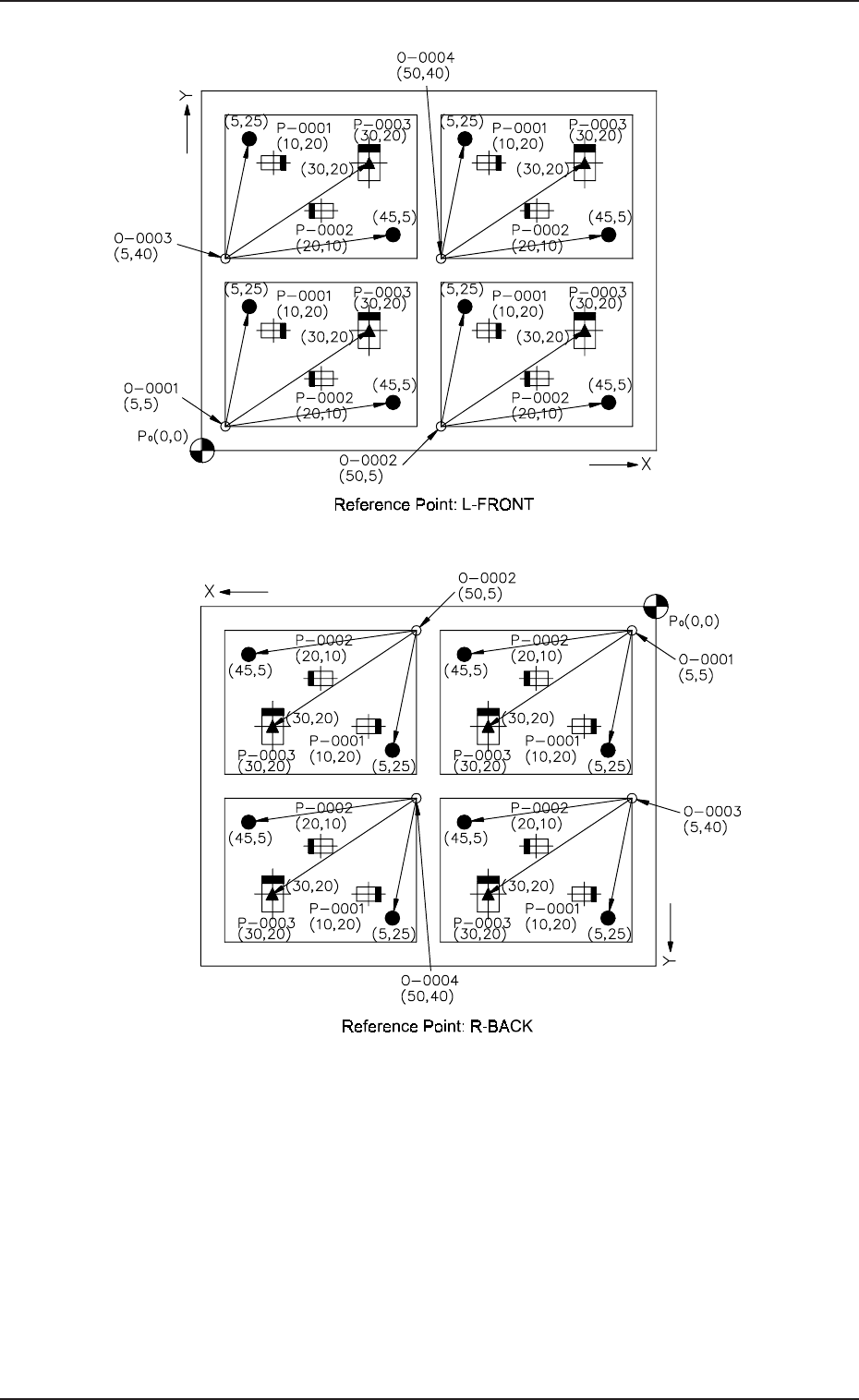
3.2 Example 2 (Example of Placement Data Creation)
Fig. 2B126
Notes: (a) P
0
shows the P.C.B. positioning reference.
(b) “O-0001”, “O-0002”, “O-0003”, and “O-0004” are called “Pat-
tern Origins”. Each coordinate measured from the P.C.B. posi-
tioning reference point must be entered.
(c) Measure the coordinates (distances) based on the pattern origins
and enter them for component placement.
(d) Measure the coordinates (distances) of the fiducial marks based
on the pattern origins and enter them.
2-80
Fig. 2B125
0305-001 Tg0858-PM-PM
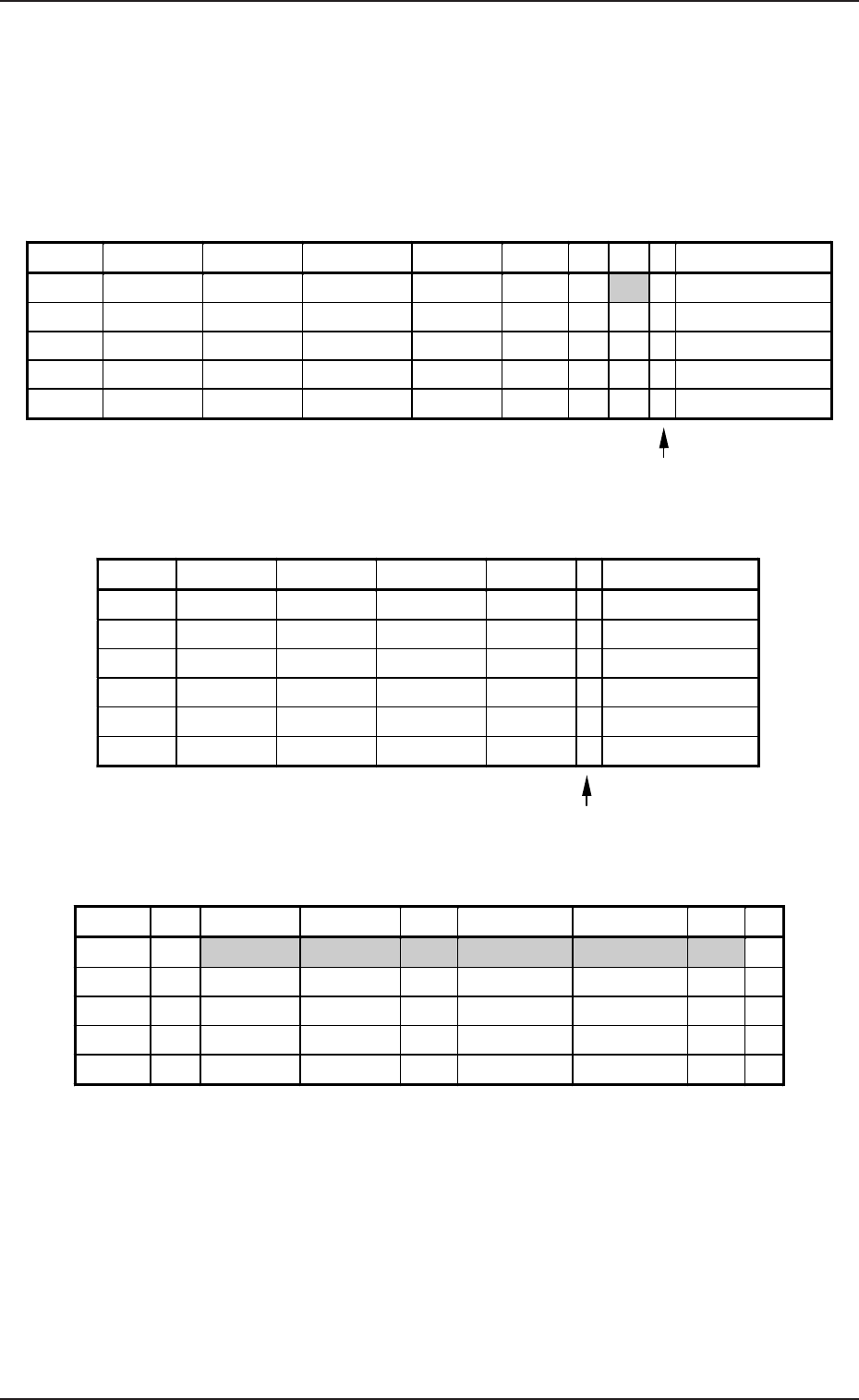
(2) Example of Data Creation
• Use placement data (P) U01 and placement data (O) U01.
• Do not enter any parameters in placement data (V) because it is not
used.
• P.E.C. recognition must be specified for each individual repetitive pat-
terns in the operation data.
(Set “ON” in the “P.E.C. RECOGNITION” and “ON” in the “IMAGE”
data box of the label “P.E.C. RECOGNITION MODE”.)
PLACEMENT DATA (P) U01
3.2 Example 2 (Example of Placement Data Creation)
2-81
Enter “0” (zero) in all data fields of the last step and “P” or
“Q” as a control command.
PLACEMENT DATA (O) U01
Enter “0” (zero) in all data fields of the last step and “E”
as a control command.
PLACEMENT DATA (V) U01
Notes: (a) The mark code Nos. registered in the “MARK DATA” data boxes
at the “OPERATION DATA” display must be entered in the “F1”
and “F2” data fields.
(b) V-0001, V-0002, V-0003 ... These Nos. correspond to the place-
ment steps.
Set these parameters to recognize a mark at the placement posi-
tion of each individual components.
In this example, the 1-point recognition is set for mark code “02”
allocated to step “P-0003”.
Do not enter any parameter unless the placement position for each
individual components should be recognized.
P-NO. X(mm) Y(mm) Z(THETA) H(mm) FDR S V C COMMENT
0000 +0.00 +0.00 +0
°
00’ +0.00 000 - 02 -
0001 +10.00 +20.00 +0
°
00’ +0.00 101 - 00 -
0002 +20.00 +10.00 +180
°
00’ +0.00 201 - 00 -
0003 +30.00 +20.00 +90
°
00’ +0.00 301 - 01 -
0004 +0.00 +0.00 +0
°
00’ +0.00 000 - 00 P
O-NO. X(mm) Y(mm) Z(THETA) H(mm) C COMMENT
0000 +0.00 +0.00 +0°00’ +0.00 -
0001 +5.00 +5.00 +0°00’ +0.00 -
0002 +50.00 +5.00 +0°00’ +0.00 -
0003 +5.00 +40.00 +0°00’ +0.00 -
0004 +50.00 +40.00 +0°00’ +0.00 -
0005 +0.00 +0.00 +0°00’ +0.00 E
V-NO. V X1(mm) Y1(mm) F1 X1(mm) Y1(mm) F2 C
0000 02 +45.00 +5.00 01 +5.00 +25.00 01 -
0001 00 +0.00 +0.00 00 +0.00 +0.00 00 -
0002 00 +0.00 +0.00 00 +0.00 +0.00 00 -
0003 01 +30.00 +20.00 02 +0.00 +0.00 00 -
0004 00 +0.00 +0.00 00 +0.00 +0.00 00 P
Table 2B27
Table 2B28
Table 2B29
0305-001 Tg0858-PM-PM
3.2 Example 2 (Example of Placement Data Creation)
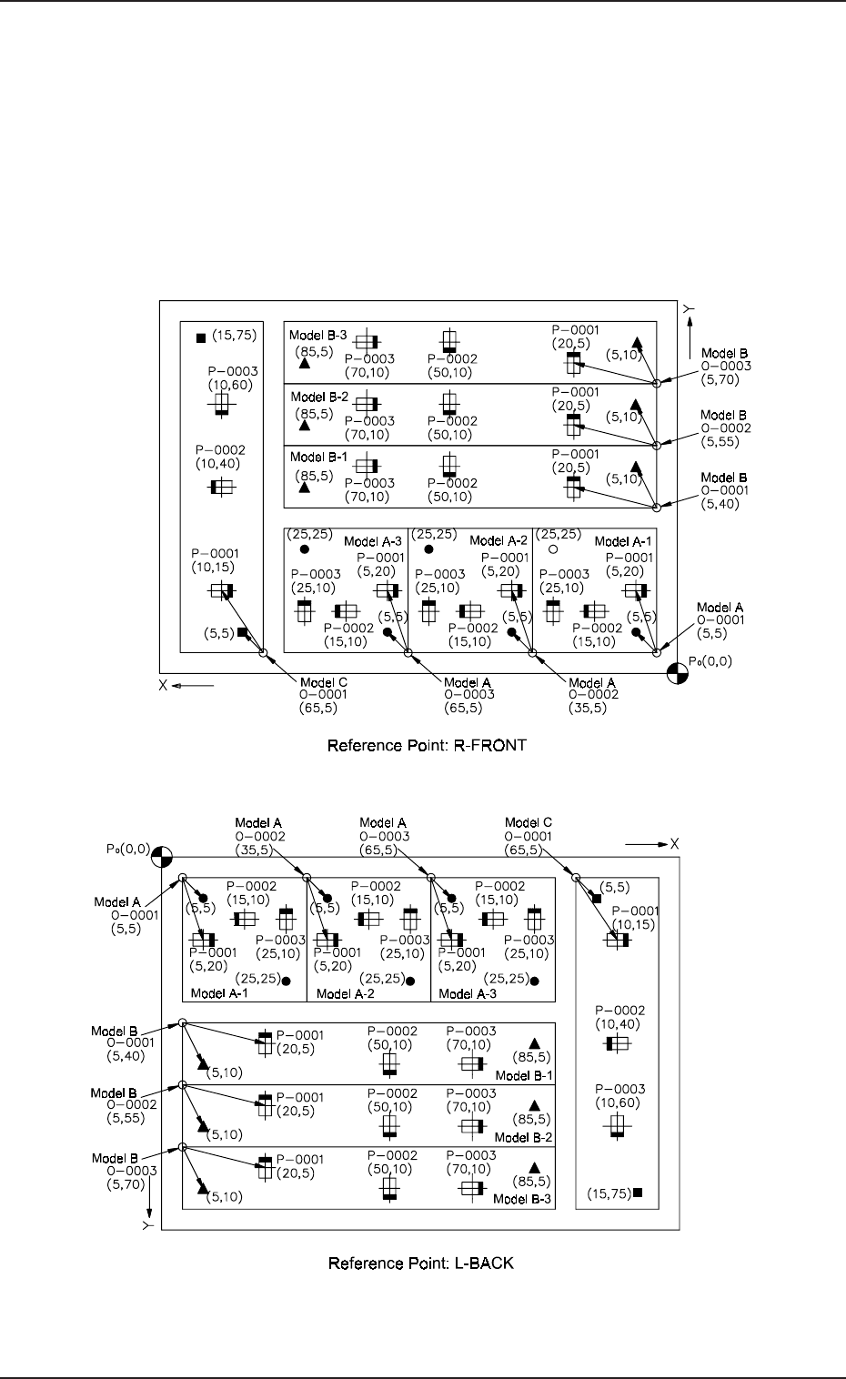
3.2.5 Placement Data for Multi-Model Repetitive Patterns
(Application for Un)
(1) Pattern Sample
• The figure below shows that the mother board has seven unit P.C.B.’s
(6 unit P.C.B.’s for models A and B and 1 unit P.C.B. for model C).
Components are placed repeatedly in regular order on each unit P.C.B.
for models A and B, forming repetitive patterns. In the case of model
C, components are placed without forming any repetitive pattern.
2-82
Fig. 2B128
Fig. 2B127