2OM-1011-002.pdf - 第190页
0305-001 Tg0858-PM-PM Third Page VIBRA TE STICK FEEDER UNIT OFFSET X (mm), Y (mm) The set offset parameters are used to adjust the positional de- viations based on the design dimensions of V ibratory Stick Feeder Units #…
0305-001 Tg0858-PM-PM
Second Page
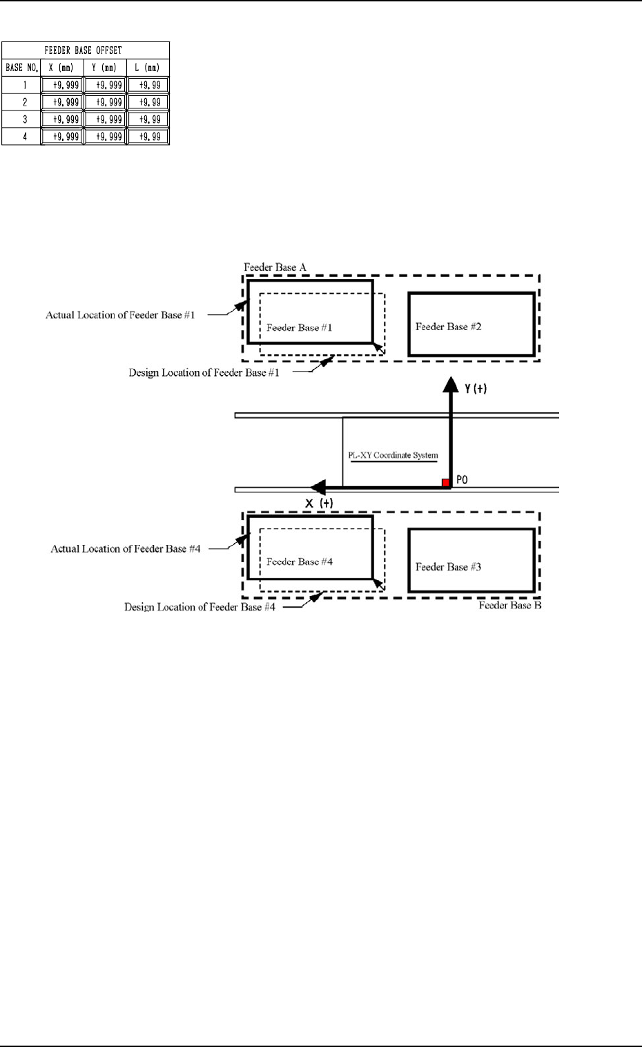
FEEDER BASE OFFSET X (mm), Y (mm)
The set offset parameters are used to adjust the positional de-
viations based on the design dimensions of Feeder Bases #1,
#2, #3, and #4 (#1 and #2 on Side A, #3 and #4 on Side B).
The values based on the PL-XY coordinate system must be
entered in the data boxes.
Ref.: The manual alignment teaching operation is possible.
When Feeder Bases #1 and #4 are located as shown below, the
offset parameters are entered with “+” (plus) signs for both “X
(mm)” and “Y (mm)”.
5-8
2. DEVICE OFFSET Display
(Front Side of Machine)
Fig. 2E30
FEEDER BASE OFFSET L (mm)
The set offset parameters are used to adjust the vertical (height
direction) deviations based on the design dimensions of Feeder
Bases #1, #2, #3, and #4 (#1 and #2 on Side A, #3 and #4 on
Side B).
When a feeder base is installed lower than the design value,
plus values must be entered.
Ref.: When the [TEACHING] key A is pressed, the “UNIT
MANUAL ALIGNMENT TEACH” display appears
on the screen.
Fig. 2E29
0305-001 Tg0858-PM-PM
Third Page
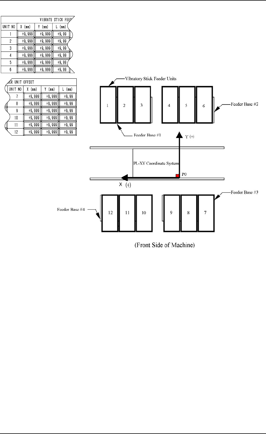
VIBRATE STICK FEEDER UNIT OFFSET X (mm), Y (mm)
The set offset parameters are used to adjust the positional de-
viations based on the design dimensions of Vibratory Stick
Feeder Units #1 through #12 (#4 through #12 are optional).
The values based on the PL-XY coordinate system must be
entered in the data boxes.
Ref.: The manual alignment teaching operation is possible.
5-9
2. DEVICE OFFSET Display
Fig. 2E32
When offset parameters are entered with “+” (plus) signs for
“X (mm)” and “Y (mm)”, the X/Y head moves in the (+) di-
rection in the PL-XY coordinate system.
VIBRATE STICK FEEDER UNIT OFFSET L (mm)
The set offset parameters are used to adjust the vertical (height
direction) deviations based on the design dimensions of Vi-
bratory Stick Feeder Units #1 through #12 (#4 through #12
are optional).
When a vibratory stick feeder unit is installed lower than the
design value, plus values must be entered.
Ref.: When the [TEACHING] key A is pressed, the “UNIT
MANUAL ALIGNMENT TEACH” display appears
on the screen.
Fig. 2E31
0305-001 Tg0858-PM-PM
Fourth Page
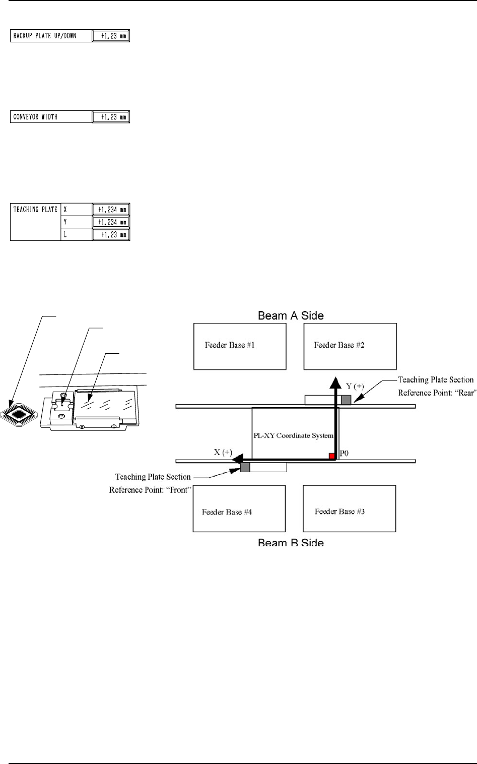
BACKUP PLATE UP/DOWN
This is the offset data for the origin position of the backup
plate up/down axis which ascends or descends during P.C.B.
positioning.
A plus (+) value decreases the ascending stroke during P.C.B.
positioning.
CONVEYOR WIDTH
This is the offset data to adjust the absolute value for the con-
veyor width. Enter the difference between the actually mea-
sured width and the data width caused when the conveyor width
is set up to the width specified by a parameter.
When the actually measured width is narrower than the width
specified by a parameter, a plus value must be entered.
TEACHING PLATE X, Y
The set offset parameters are used to adjust the positional de-
viations based on the design dimensions of the teaching plate
(the glass jig used for automatic teaching operation of various
offset data) stock position. The values based on the PL-XY
coordinate system must be entered in the data boxes.
Note: The teaching plate section differs according to the ref-
erence position of the machine.
Ref.: The manual alignment teaching operation is possible.
Fig. 2E37
When offset parameters are entered with “+” (plus) signs for
“X (mm)” and “Y (mm)”, the X/Y head moves in the (+) di-
rection in the PL-XY coordinate system.
TEACHING PLATE L
The set offset parameter is used to adjust the vertical (height
direction) deviation based on the design dimension of the teach-
ing plate (the glass jig used for automatic teaching operation
of various offset data) stock position.
When the teaching plate is installed lower than the design value,
a plus value must be entered.
Ref.: When the “X”, the “Y”, or the “L” data box of the
label “TEACHING PLATE” is selected, the [TEACH-
ING] key appears at A.
When this key is pressed, the “UNIT MANUAL ALIGN-
MENT TEACH” display appears on the screen.
5-10
2. DEVICE OFFSET Display
Fig. 2E36
Teaching Plate Section
Fig. 2E33
Fig. 2E34
Fig. 2E35
Teaching Plate
Teaching Plate
Stock Position
Back Light
Stage