2OM-1011-002.pdf - 第132页
0305-001 Tg0858-PM-PM (2) When the key of the step where the data to be edited is pressed then the corresponding setting window appears on the screen. Fig. 2B164 [CHNG] Key Fig. 2B165 4.5 COMPONENT DA T A Display (3) Mov…
0305-001 Tg0858-PM-PM
4.5 COMPONENT DATA Display
• Press the [STEP INSERT] or the [STEP DELETE] key to insert or
delete the data line (step) of the feeder slot No. where the line cursor is
located.
• When the [PROGRAM CHECK] key is pressed, the edited pattern
program is checked.
(7) When the [RTN] key is pressed, the “COMPONENT DATA -TRAY-”
display appears on the screen.
• When one of the [TRAY L] keys is pressed at the “COMPONENT
DATA -TRAY-” display for “Tray L” or “Tray R”, the “COMPONENT
DATA -TRAY-” display for the tray feeder unit (Tray L) installed on
the left side appears on the screen. Pressing one of the [TRAY R] keys
opens the “COMPONENT DATA -TRAY-” display for the tray feeder
unit (Tray R) on the right side.
4.5.3 Editing of Tray Steps Information Data (Option)
Operation Procedure
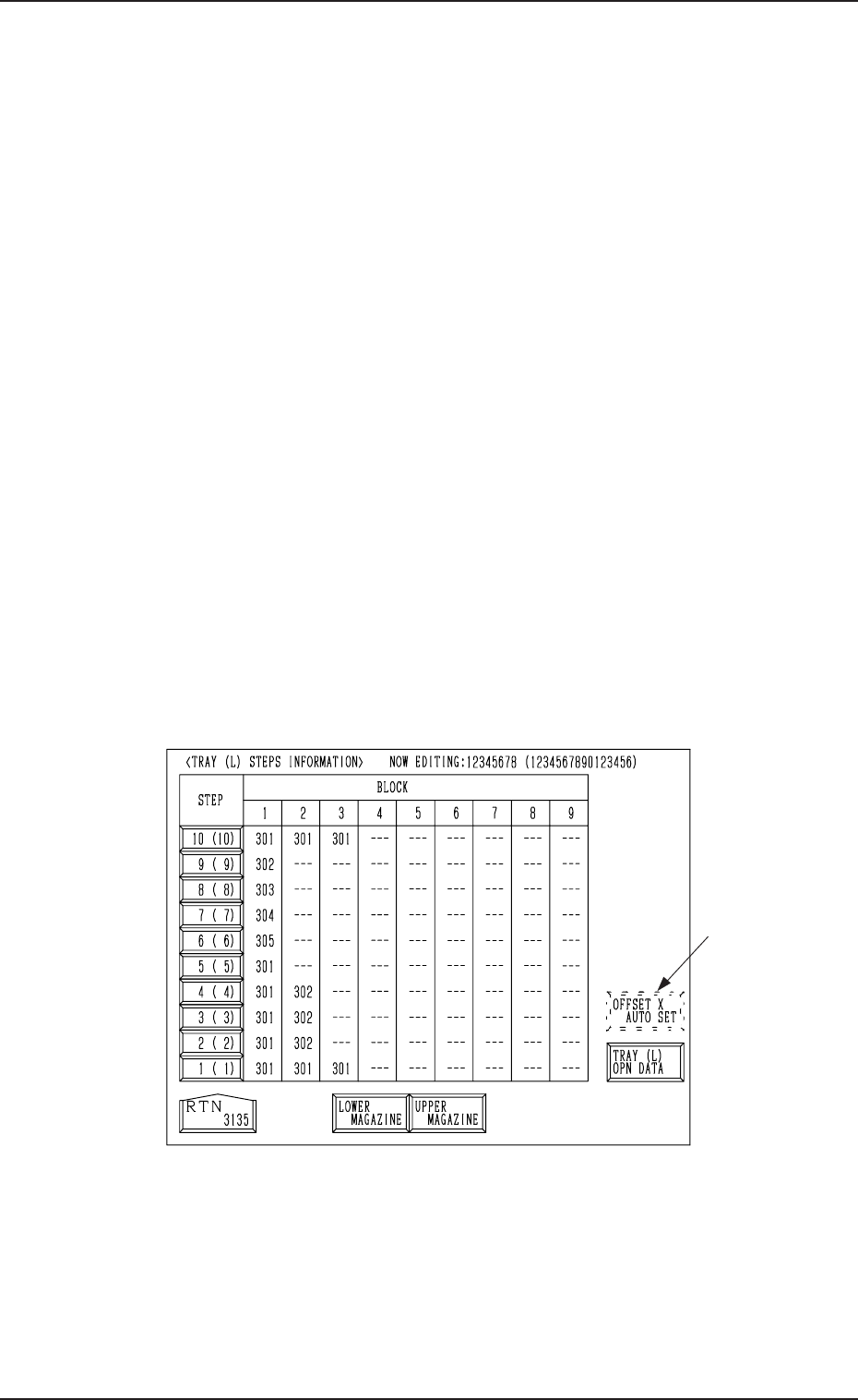
(1) When the [TRAY STEP INFO] key is pressed at the “COMPONENT
DATA -TRAY-” display (Fig. 2B160) for “Tray L”, the following display
appears on the screen.
While the system is in the edit mode of the component data for “Tray L”,
the “COMPONENT DATA -TRAY-” display shows the step information
for “Tray L”. In the edit mode of the component data for “Tray R”, the
display shows the step information for “Tray R”.
Fig. 2B163
• Press the [LOWER MAGAZINE] key to select the lower magazine.
Pressing the [UPPER MAGAZINE] key selects the upper magazine.
Note: The [OFFSET X AUTO SET] key *1 may not appear, depending
on how the feeder Nos. (FDR NO) are set.
Consult our sales personnel for details.
2-112
*1
0305-001 Tg0858-PM-PM
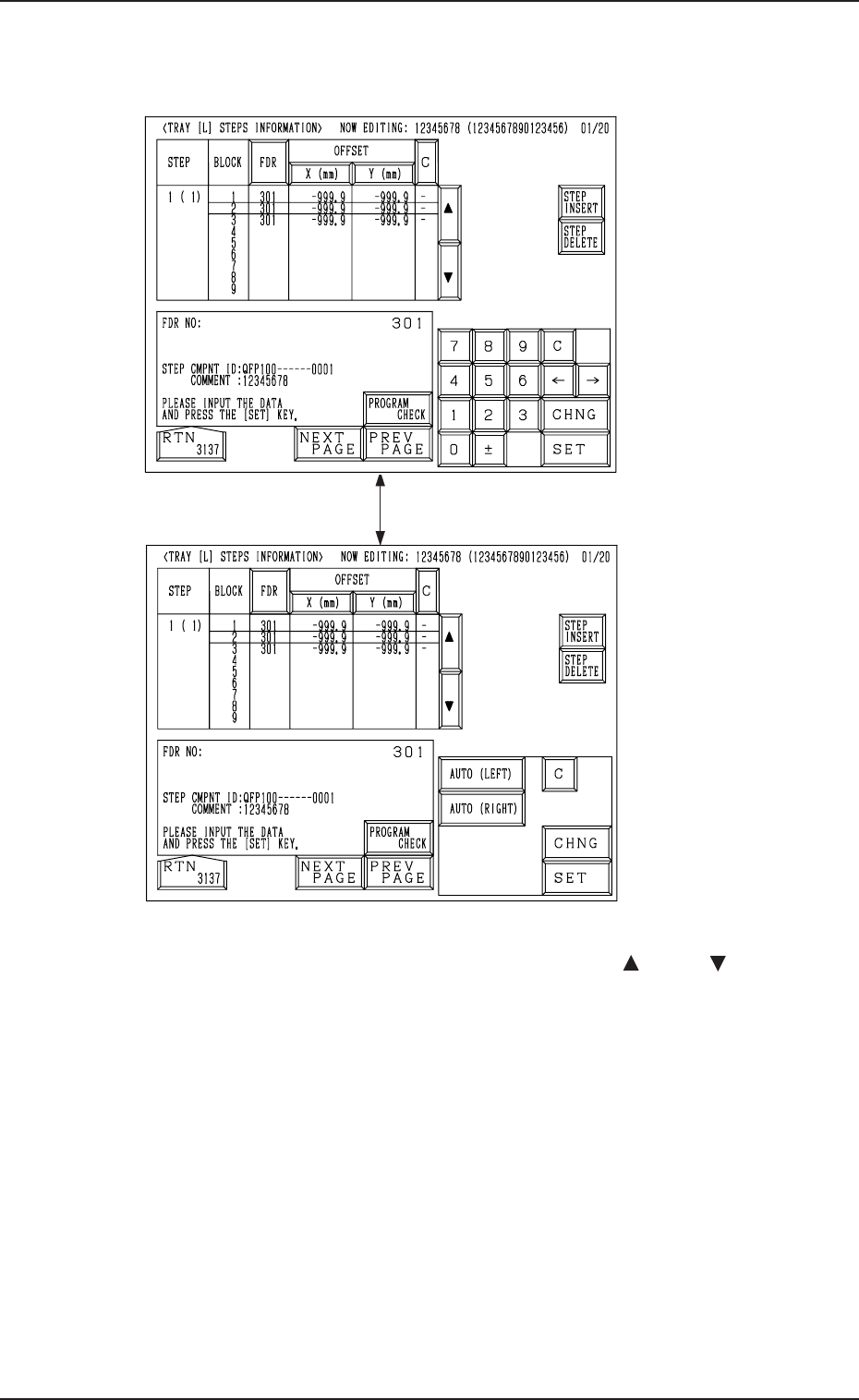
(2) When the key of the step where the data to be edited is pressed then the
corresponding setting window appears on the screen.
Fig. 2B164
[CHNG] Key
Fig. 2B165
4.5 COMPONENT DATA Display
(3) Move the line cursor to the block to be edited with the [ ] or the [ ] key.
(4) Select the [FDR] key and set the component to be specified for the se-
lected block of the step.
It is required to set the component ID for the feeder slot No. (FDR NO) in
advance by editing the component data.
(5) Edit the component data as follows.
• Select the [X (mm)] key and specify Reference Point X for the block.
It is required to select either the [AUTO (LEFT)] or the [AUTO
(RIGHT)] key for the reference point. The tray reference coordinates
(based on the pallet reference position) must also be entered.
• Select the [Y (mm)] key and specify Reference Point Y for the block.
• When the [C] key is selected, a control command can be entered.
• Press the [STEP INSERT] or the [STEP DELETE] key to insert or
delete the data line (step) of the feeder slot No. where the line cursor is
located.
• When the [PROGRAM CHECK] key is pressed, the edited pattern
program is checked.
2-113
0305-001 Tg0858-PM-PM2-114
4.5 COMPONENT DATA Display
4.5.4 Editing of Tray Operation Data (Option)
Operation Procedure
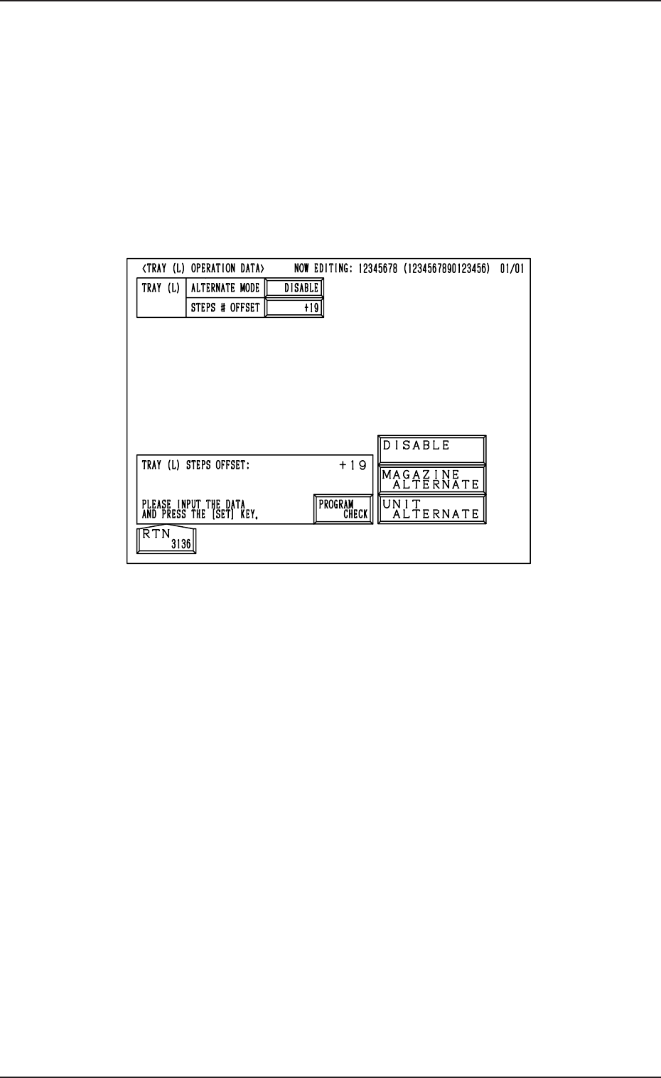
(1) When the [TRAY (L) OPN DATA] key is pressed at the “TRAY (L) STEPS
INFORMATION” display (Fig. 2B163), the following display appears on
the screen.
When the [TRAY (R) OPN DATA] key is pressed at the “TRAY (R) STEPS
INFORMATION” display, the “TRAY (R) OPERATION DATA” display
appears on the screen.
Fig. 2B166
(2) • Set the magazine alternate function.
Press the “MAGAZINE ALTN” key and select [DISABLE], [MAGA-
ZINE ALTERNATE] or [UNIT ALTERNATE] and then press the
[SET] key.
• Enter an offset value in the “STEPS # OFFSET” data box and press
the [SET] key.
(3) Press the [RTN] key to open the “TRAY (L) STEPS INFORMATION”
display.
What is Alternate Function?
This function reduces the downtime of the system when any component short-
age error occurs, by shifting the component pick-up position to the designated
position in due order and without stopping the system.