2OM-1011-002.pdf - 第61页
0305-001 Tg0858-PM-PM 2-42 2.5 COMPONENT DA T A Display *1 AL TERNA TE FDR. [MODE] Key : “ON” or “OFF” can be set to determine whether or not the alternate feeder function should be used. Ref.: It is recommended to set i…
0305-001 Tg0858-PM-PM
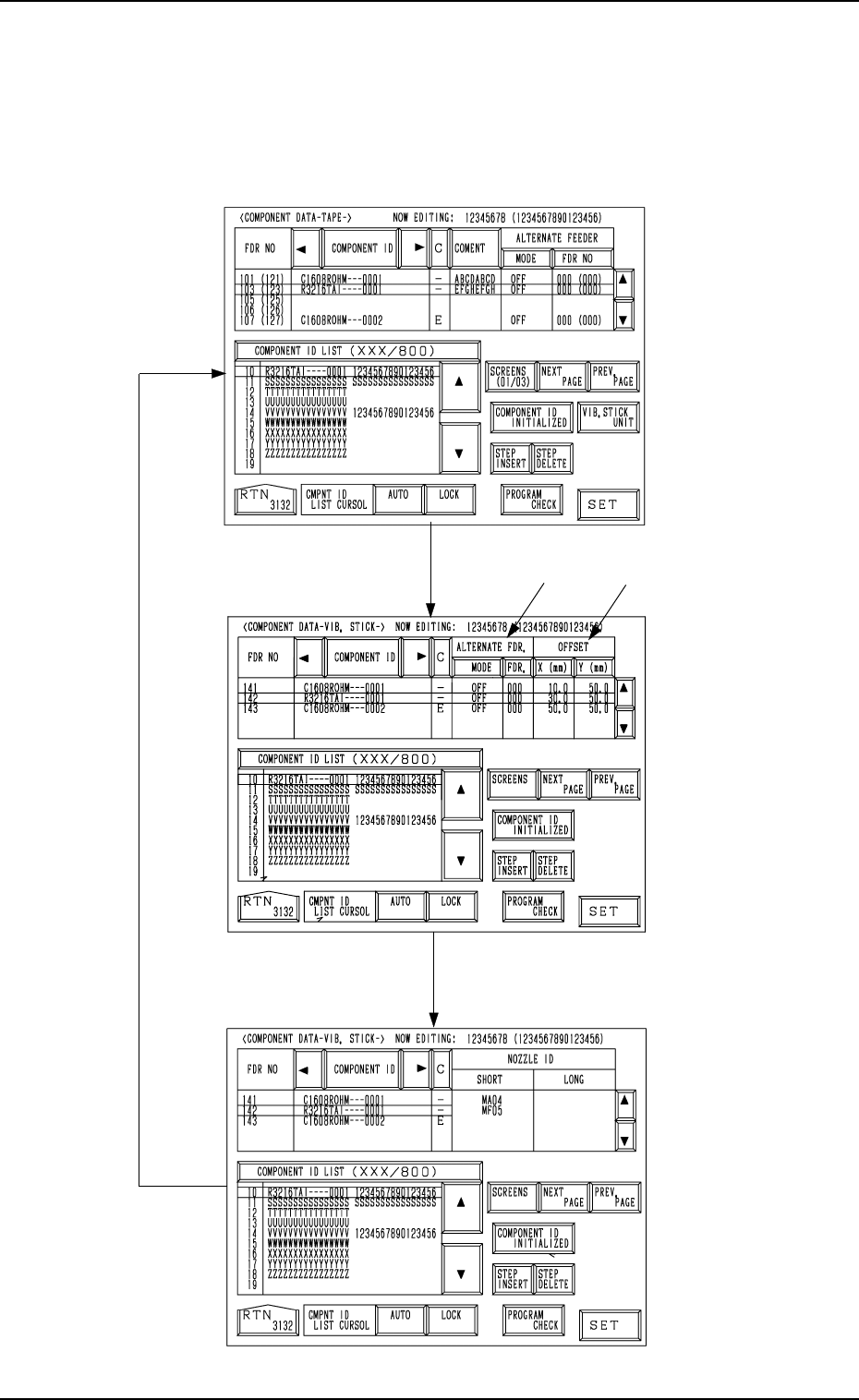
2.5.2 Vibratory Stick Feeders
When the [DATA EDIT] key is pressed at the display (Fig. 2B80) for “Vibra-
tory Stick Feeder A”, the following display appears on the screen.
Every time the [SCREENS] key is pressed, another display appears on the
screen.
*1
*2
Fig. 2B89
[SCREENS] Key
Fig. 2B90
Fig. 2B91
2-41
2.5 COMPONENT DATA Display
0305-001 Tg0858-PM-PM2-42
2.5 COMPONENT DATA Display
*1 ALTERNATE FDR.
[MODE] Key : “ON” or “OFF” can be set to determine whether or not
the alternate feeder function should be used.
Ref.: It is recommended to set it to "OFF".
[FDR.] Key : When a component pick-up error occurs continuously
(Component Library: ERROR PROCESS DATA 1 and
2), the destination feeder No. for alternate use can be speci-
fied.
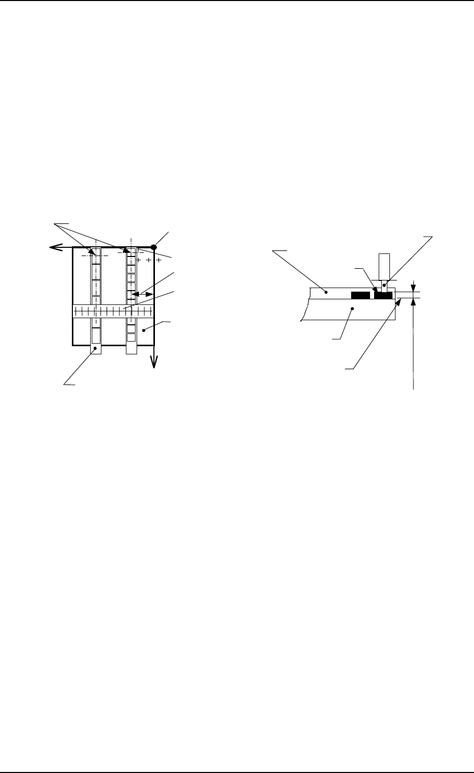
*2 OFFSET
[X (mm)] : Enter the distance in the X direction between the reference
position of the vibratory stick feeder unit and the pick-up po-
sition.
[Y (mm)] : Enter the distance between the end (pushing face) of the vibra-
tory stick feeder and the pick-up position.
Vacuum Nozzle
Carrier Stick Magazine
Carrier Stick Magazine
Component
Pick-Up Level
(Component Library)
X
+
+
Y
Pick-Up Points
Position Offset Y
Position Offset X
Reference Point of Pick-Up Level
Reference Point of Vibratory Stick Feeder Unit
Vibratory Stick
Feeder Unit
Vibratory Stick
Feeder Unit
X Direction Offset
Reading Gauge
Fig. 2B92
0305-001 Tg0858-PM-PM
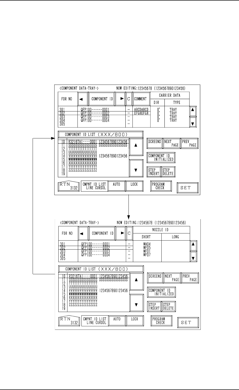
2.5.3 Tray Feeders (Option)
When the [DATA EDIT] key is pressed at the display for “TRAY L” (Fig.
2B83), the following display appears on the screen.
Every time the [SCREENS] key is pressed, another display appears on the
screen.
Associate component IDs by using the feeder Nos. (301 to 599) allocated to
Tray L.
Fig. 2B93
[SCREENS] Key
Fig. 2B94
2.5 COMPONENT DATA Display
2-43