2OM-1011-002.pdf - 第76页
0305-001 Tg0858-PM-PM 2-57 2.6 Placement Data H (mm) Set the placement height of component. T o increase the descending stroke of the head for component placement, a plus value must be entered. • The set parameter is use…
0305-001 Tg0858-PM-PM2-56
2.6 Placement Data
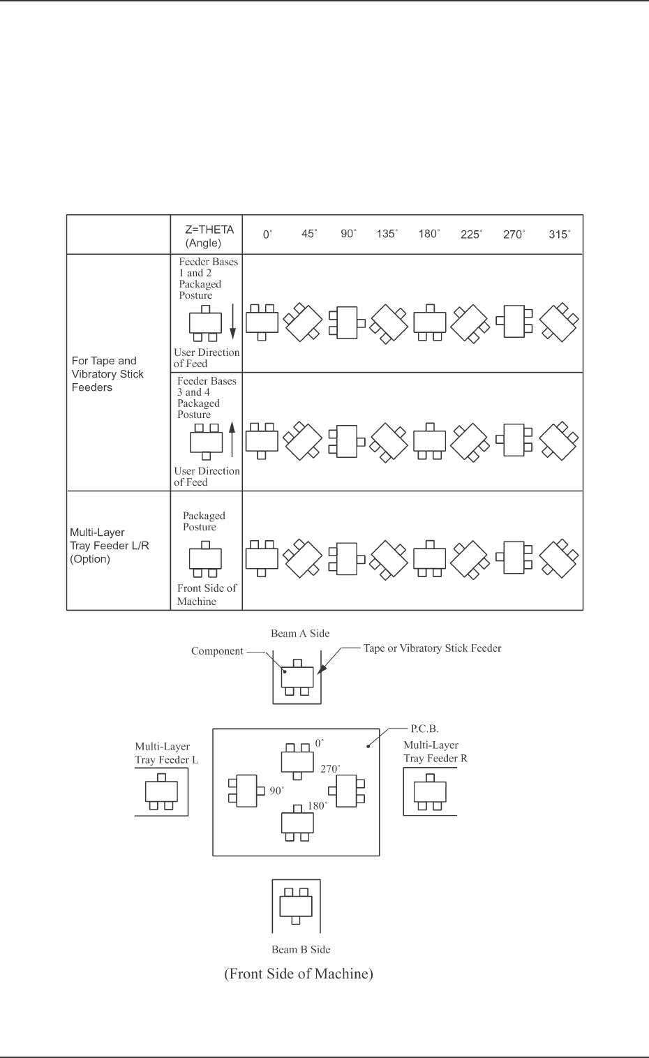
Z=THETA (Angle)
Set component placement angle data Z.
• Data Input Range: 0°00´ to 359°59´
• Offset value must be entered as placement angle offset in the data field
of step P-0000 labeled “Z=THETA”.
The offset values can be entered in the range “-99°99´ to +99°99´ ” with
+ or - sign.
Note: The following shows the placement angles changed from the pack-
aged posture of a component.
Table 2B5
Fig. 2B108
0305-001 Tg0858-PM-PM2-57
2.6 Placement Data
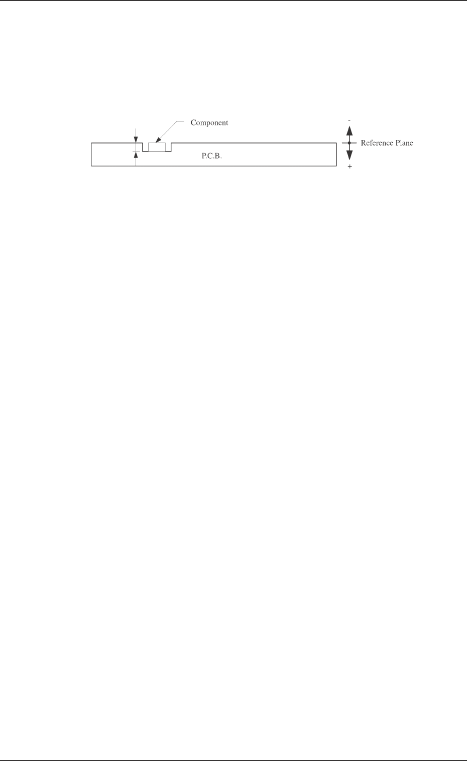
H (mm)
Set the placement height of component.
To increase the descending stroke of the head for component placement, a
plus value must be entered.
• The set parameter is used to cope with concave sections of a P.C.B. and
convex sections of a daughter P.C.B.
• The “H” data in the P-0000 step is reflected on all steps.
FDR
Set a feeder No. (component-allocated slot No.).
• Data Input Range
101 to 109, 121 to 139, 201 to 219, 221 to 239
Note: The feeder No. set here must be specified in the component data.
• Components are picked up from the set feeder No. (slot No.).
The component No. offset is added to the feeder slot No. from which
components are actually picked up.
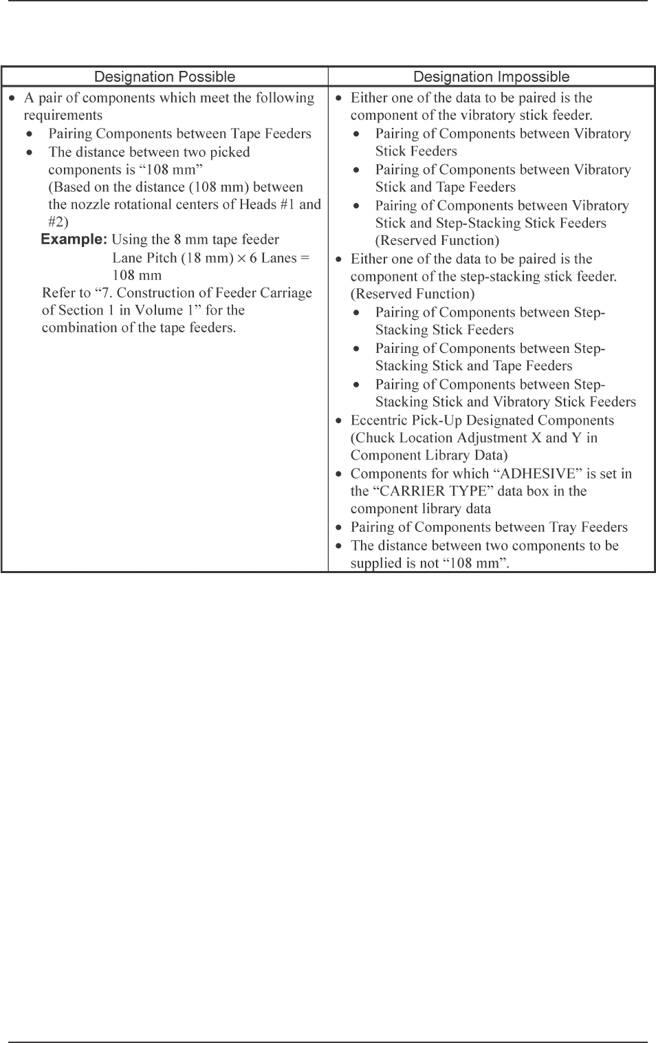
S
Shown is the sequence in which components are picked up.
By specifying “1” or “2” as the S data, a pair of placement steps can be
made.
- : Individual Component Pick-Up/Placement
This shows that the number of cutting blocks is “1 step”.
1 : Simultaneous Pick-Up
The number of cutting blocks is “2 steps” (current and subsequent steps).
Components are recognized and placed in the order specified in the
placement data.
2 : Pick-Up Priority
The number of cutting blocks is “2 steps” (current and subsequent steps).
Components are picked up, recognized and placed in the order speci-
fied in the placement data.
Note: When the simultaneous pick-up and chuck position automatic fol-
low-up functions are used together, the chuck position automatic
follow-up function works based on the results of the component
recognition for the first step of the paired two placement steps. There-
fore, a hindrance may be caused at the other component pick-up
position. Especially, when small components are picked up simul-
taneously or components which require delicate picks are handled,
it is recommended that the pick-up priority function should be used.
• To designate the individual pick-up/placement, set “-” as the S
data.
In the following cases, “Individual Pick-Up/Placement” must be
specified because no pairing (2-step processing) can be made.
• Components whose dimension (width) exceeds 50 mm are
handled. (Component Collision due to Rotation)
• Components subjected to the divided recognition are handled.
Fig. 2B109
0305-001 Tg0858-PM-PM
• To designate the simultaneous pick-up (“1” to be set as “S” data)
2-58
2.6 Placement Data
Table 2B6