2OM-1011-002.pdf - 第50页
Fig. 2B68 [PROGRAM CHECK] Key When this key is pressed, the edited pattern program is checked. CONVEYOR WIDTH Set one of the followings in the data box to determine whether or not the conveyor width should be set up auto…
2.3 OPERATION DATA Display
(2) Material
• Copper Leaf
(Au and Ni plating possible but mirror surfaces cannot be used.)
• Solder Plating (Consult our sales personnel.)
• Solder Leveler (Consult our sales personnel.)
(3) Specifications of Lines extended from a Pad Mark or a Through Hole
(Unit: mm)
Fig. 2B67
(c) The shape of P.C.B. (a cutout, a punched hole), the exter-
nal elements (light reflected from a structure, light emitted
from an external device, etc.) may sometimes interfere with
recognition. Consult our sales personnel for details.
(d) A fiducial mark should make ample contrast with the sur-
roundings. (To prevent false recognition)
(e) Anything resembling a pattern similar to a fiducial mark
should not exist in the designated window. If one exists, it
may cause false recognition.
(f) A test may be required when the fiducial mark cannot be
recognized because of the extreme warpage of the P.C.B.
Fig. 2B66
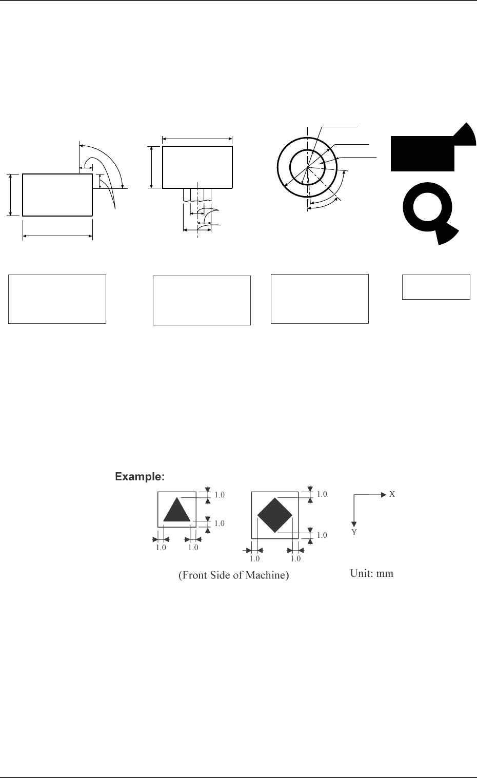
Notes: (a) A through hole or a pad mark should have only one land
which is directed in increments of 45°. Consult our sales
personnel for details (dimensions, etc.).
(b) A copper leaf, a resist, a coating, a silk print, and a punched
hole should not exist in the range of 1.0 mm in both X and
Y directions from the outermost edges of a fiducial mark.
They may cause false recognition.
0305-001 2-30
Tg0858-PM-PM
Range between Lines
and Tangential Lines
1/3 of Shorter Side
0.5 to 2.0
0.5 to 2.0
0.5 to 2.0
0.5 to 2.0
1/3 of Shorter Side
Range between Lines
and Tangential Lines
0.5 to 1.5
1.0 to 2.0
Min. 0.25
80° (Range
between Lines
and Tangential
Lines)
(Front Side of Machine)
45°
Pad Mark 45°
Range of Land Location
in Increments of 45° for
Pad mark
Pad Mark 90°
Range of Land Location
in Increments of 90° for
Pad mark
Range of Land Location
for Through Hole
(45° at the bottom right
of the hole)
Examples of Land
Locations
(Front Side of Machine)
(Front Side of Machine)
(Front Side of Machine)
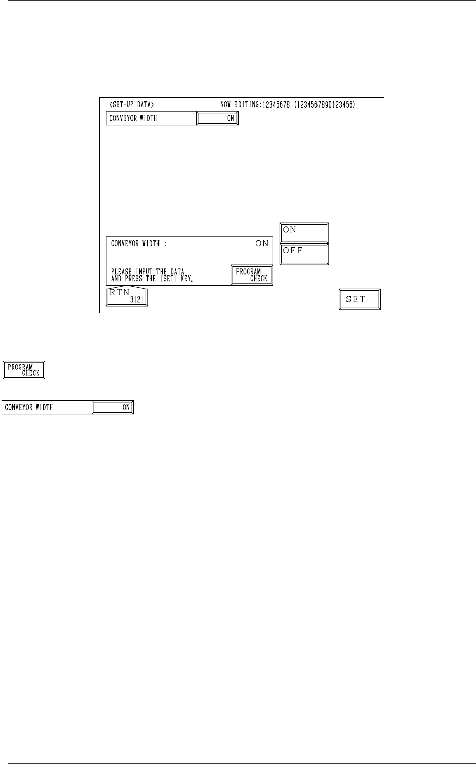
Fig. 2B68
[PROGRAM CHECK] Key
When this key is pressed, the edited pattern program is checked.
CONVEYOR WIDTH
Set one of the followings in the data box to determine whether
or not the conveyor width should be set up automatically.
“ON”
“OFF”
When the pattern program for which “ON” is set is changed
by pressing the [MOVE] button, the conveyor width is auto-
matically set up and changed in accordance with the param-
eter set in the “Y (vertical)” data box of the label “P.C.B. SIZE”
at the “OPERATION DATA” display.
2.4 SET-UP DATA Display
When the [SET-UP DATA] key is pressed at the “PATTERN PROGRAM
EDIT” display, the following display appears on the screen.
2.4 SET-UP DATA Display
0305-001 2-31 Tg0858-PM-PM
Fig. 2B69
Fig. 2B70
0305-001 Tg0858-PM-PM
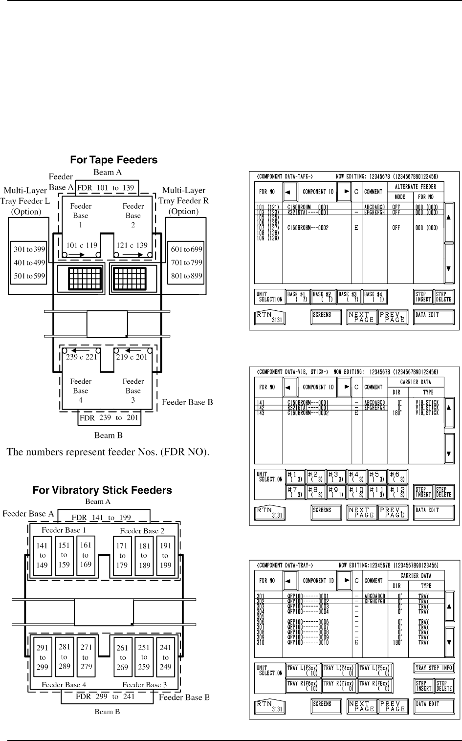
2.5 COMPONENT DATA Display
When the [TAPE [A] (F101-F139)], the [VIB STICK [A] (F141-F199)], or the
[TRAY L (F301-F599)] key is pressed at the “PATTERN PROGRAM EDIT”
display, the corresponding display (Fig. 2B73, 2B74, or 2B75) appears on the
screen.
When the [TAPE [B] (F201-F239)], the [VIB STICK [B] (F241-F299)], or the
[TRAY R (F601-F899)] key is pressed, the corresponding display (similar to
Fig. 2B73, 2B74, or 2B75) appears on the screen.
Fig. 2B71
Fig. 2B75
Fig. 2B74
Fig. 2B73
[TEAP A]
[VIB. STICK A]
[TRAY L]
Fig. 2B72
2.5 COMPONENT DATA Display
2-32