2OM-1011-002.pdf - 第156页
0305-001 Tg0858-PM-PM 1. DEVICE DA T A Display The P .C.B. transfer mode (P .C.B. reception from the input machine and trans- fer to the output machine) and the device timers can be set. When the [DEVICE DA T A] key is p…

0305-001 Tg0858-PM-PM3-B
0305-001 Tg0858-PM-PM
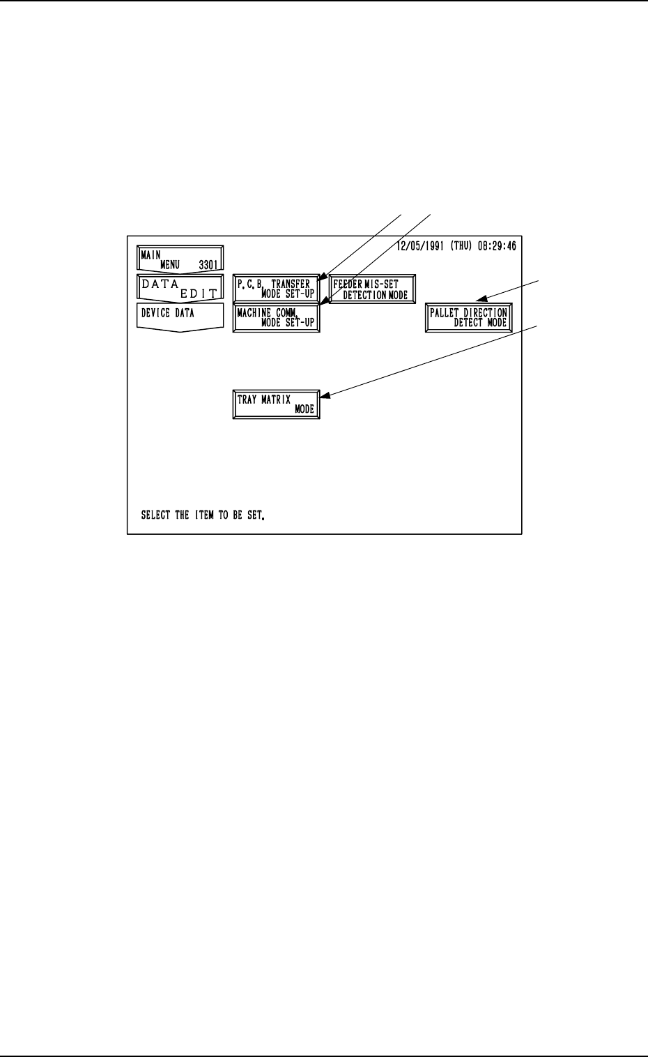
1. DEVICE DATA Display
The P.C.B. transfer mode (P.C.B. reception from the input machine and trans-
fer to the output machine) and the device timers can be set.
When the [DEVICE DATA] key is pressed at the “DATA EDIT” display, the
following display appears on the screen.
*1
*2
*3 (Option)
1. DEVICE DATA Display
3-1
Fig. 2C1
*1 [P.C.B. TRANSFER MODE SET-UP] Key
Various parameters can be set when P.C.B.’s are produced mainly in the in-
line system.
(P.C.B. transfer mode, conditions, etc., can be set.)
*2 [MACHINE COMM. MODE SET-UP] Key
The machine address can be set for data communication with an external
device (such as the programming device).
*3 [TRAY MATRIX MODE] Key (Option)
When this key is pressed, the “TRAY MATRIX MODE” display appears
on the screen, enabling you to designate the direction in which the tray
matrix should be updated.
(When it is necessary to keep the interchangeability with TIM-1000 and
TIM-1100 series, set “X DIR.” in the “TRAY MATRIX MODE” data box
at the “TRAY MATRIX MODE2 display.)
*4 PALLET DIRECTION DETECT MODE
This sets whether or not the pallet direction should be detected.
*4
0305-001 Tg0858-PM-PM
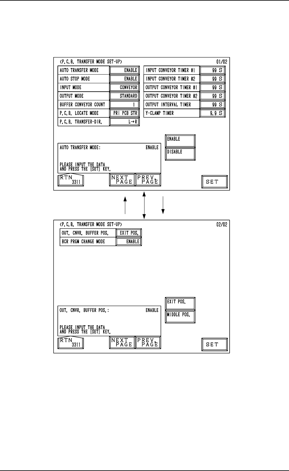
2. P.C.B. TRANSFER MODE SET-UP Display
2. P.C.B. TRANSFER MODE SET-UP Display
When the [P.C.B. TRANSFER MODE SET-UP] key is pressed at the “DE-
VICE DATA” display, the following display appears on the screen.
3-2
Fig. 2C2
Fig. 2C3