2OM-1011-002.pdf - 第161页
0305-001 Tg0858-PM-PM P .C.B. LOCA TE MODE Set the sequence in which a P .C.B. should be transferred and positioned. Select “PRI PCB STR” or “PLACE REF .”. “PRI PCB STR” : Select this when the placement coordinates refer…

0305-001 Tg0858-PM-PM
OUTPUT MODE
Select “STANDARD” or “INTERVAL” according to the P.C.B.
loading system of the output machine.
• “STANDARD” Mode
When the output machine is connected with our machine (a
component placement machine, a dispenser, a printer, or a
multi-functional component placement machine), set
“STANDARD” in the data box.
When the P.C.B. requirement signal is received from the
output machine, the P.C.B. transfer signal of the machine is
turned ON and a P.C.B. is discharged to the output machine
by the output conveyor.
When the P.C.B. requirement signal is not turned OFF within
the specified time after P.C.B. unloading action has started,
the machine stops in an error condition.
• “INTERVAL” Mode
When the machine receives the P.C.B. requirement signal
from the output machine, it does not transmit any response
signal (no handshaking) and starts discharging P.C.B.’s.
The conveyor stops when the output conveyor timer has
reached the specified time.
When the requirements for P.C.B. output are fulfilled after
the conveyor has stopped and the output interval timer has
reached the time set in the “OUTPUT INTERVAL TIMER”
data box, the machine starts the P.C.B. output operation.
(No Error Detection)
BUFFER CONVEYOR COUNT
Set the number of P.C.B. buffers on the input conveyor in this
data box.
• “0”, “1”, or “2” can be set in the data box.
Note: The parameter “2” becomes valid only EL/ER conveyor
(option) is installed on the input side.
3-5
2. P.C.B. TRANSFER MODE SET-UP Display
Fig. 2C6-2
0305-001 Tg0858-PM-PM
P.C.B. LOCATE MODE
Set the sequence in which a P.C.B. should be transferred and
positioned.
Select “PRI PCB STR” or “PLACE REF.”.
“PRI PCB STR” : Select this when the placement coordinates
reference for the P.C.B. must be specified
on the opposite side of the P.C.B. stopper
location for P.C.B. positioning.
“PLACE REF.” : Select this when the placement coordinates
reference must be specified on the side
where the P.C.B. is pushed against the
P.C.B. stopper.
Refer to “6.5 P.C.B. Transfer of Section 1 in Volume 1” for
details.
Notes: (a) The direction of the P.C.B. stopper block is ad-
justed in compliance with the setting upon ship-
ment of the machine.
When the setting is changed, it is required to
change the direction of the P.C.B. stopper block
according to the changed setting.
Refer to “Section 2 Adjustment of P.C.B. Posi-
tioning Section in Volume 5” for details.
(b) Push the P.C.B. against the P.C.B. stopper for
positioning.
When an area of the P.C.B. has a cutout, etc.,
and is pushed against the P.C.B. stopper, the
P.C.B. cannot be positioned correctly.
(c) When a P.C.B. is positioned by the pilot pin (op-
tion), set “PLACE REF.” in the data box.
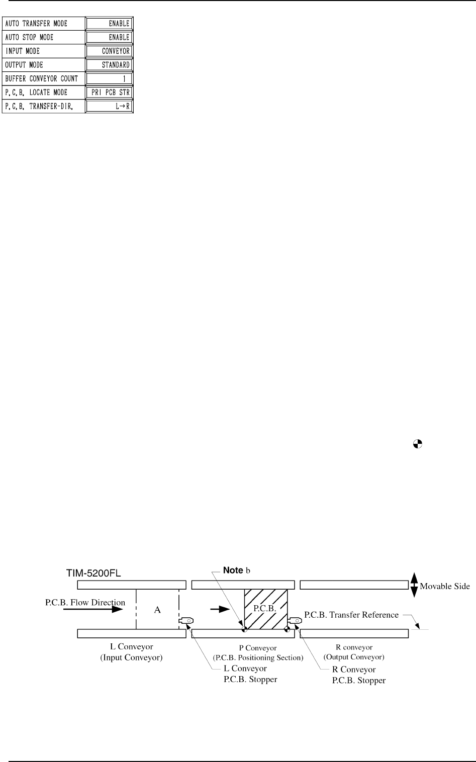
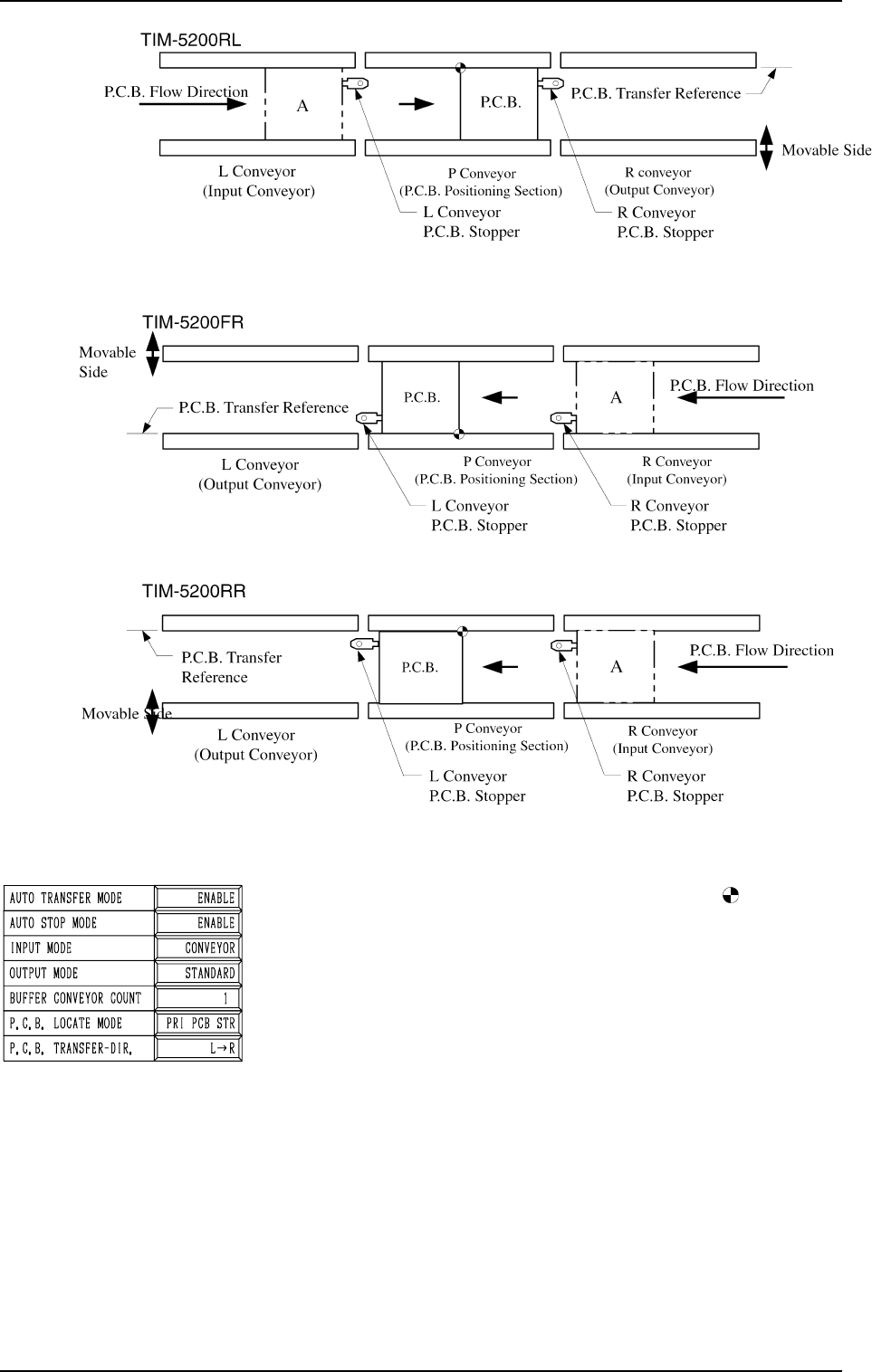
[PRI PCB STR] (Placement Coordinates Reference: )
P.C.B.s are positioned on the P.C.B. stopper located in the
upstream of the P.C.B. flow direction.
Scope of Positioning
(1) The P.C.B.’s at standby position A in the figures below
are sent to the P.C.B. stoppers.
(2) The P.C.B. backup base ascends and works to position
the P.C.B. vertically and horizontally (alignment in Y
direction).
2. P.C.B. TRANSFER MODE SET-UP Display
3-6
Fig. 2C8
Fig. 2C7
0305-001 Tg0858-PM-PM
[PLACE REF.] (Placement Coordinates Reference: )
Priority is given to the placement coordinates reference for
positioning.
Scope of Positioning
(1) The P.C.B.’s at Standby Position A in the figures be-
low are sent ahead of the P.C.B. stoppers for position-
ing.
(2) An action takes place to bring the P.C.B. back to the
P.C.B. stopper for positioning.
(3) The P.C.B. backup base ascends and works to position
the P.C.B. vertically and horizontally (alignment in Y
direction).
Note: Because an action takes place to return the P.C.B.
at P.C.B. positioning, the P.C.B. transfer time be-
comes longer, compared with the time required
when “PRI PCB STR” is set in the data box.
Fig. 2C9
2. P.C.B. TRANSFER MODE SET-UP Display
Fig. 2C10
Fig. 2C11
3-7
Fig. 2C12