2OM-1011-002.pdf - 第208页
0305-001 Tg0858-PM-PM 7. NOZZLE STOCKER OFFSET Display 5-27 BEAM-A NOZZLE STOCKER [A1] The set of fset data is used to adjust the positional deviations based on the design dimensions representing the nozzle stocker unit …
0305-001 Tg0858-PM-PM
7. NOZZLE STOCKER OFFSET Display
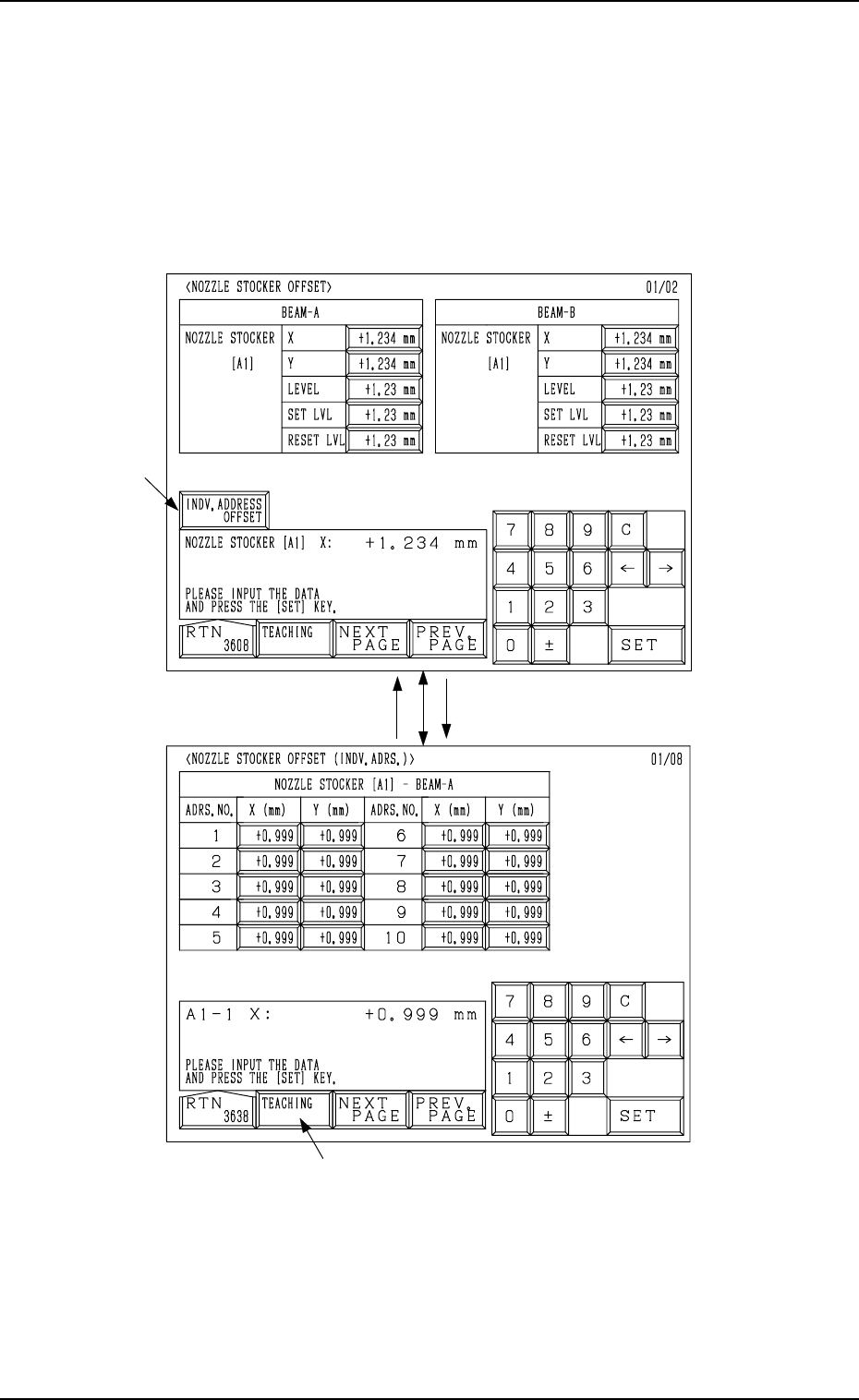
• This offset data is used to adjust the position of the nozzle stocker unit
based on “P.C.B. Positioning Reference: P0”.
When the [NOZZLE STOCKER OFFSET] key is pressed at the “OFFSET
DATA” display, the following display appears on the screen.
Every time the [NEXT PAGE] or the [PREV. PAGE] key is pressed, another or
previous page appears on the screen.
Fig. 2E69
Fig. 2E70
*2
*1
7. NOZZLE STOCKER OFFSET Display
Ref.: When the [TEACHING] key *2 is pressed, the “UNIT MANUAL
ALIGNMENT TEACH” display appears on the screen.
Refer to “6.8.5 Nozzle Stocker Offset of Section 3 in Volume 4” for
details.
5-26
When the *1 [INDV. ADDRESS OFFSET] key
is pressed, the following display appears.
0305-001 Tg0858-PM-PM
7. NOZZLE STOCKER OFFSET Display
5-27
BEAM-A NOZZLE STOCKER [A1]
The set offset data is used to adjust the positional deviations based on the
design dimensions representing the nozzle stocker unit position viewed from
the X/Y coordinate system (PL-XY: Origin P0) for P.C.B. positioning.
The values based on the PL-XY coordinate system must be entered in the
data boxes.
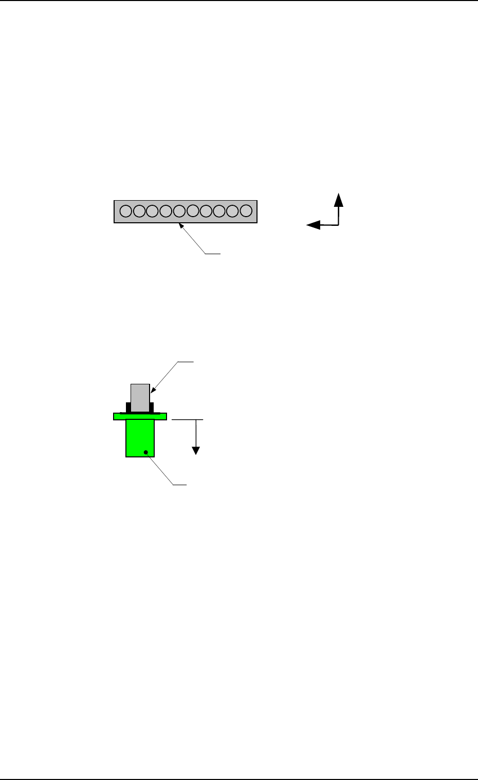
Set the values which represent the positional deviations of Nozzle Stocker
A1 based on Beam A.
X (Horizontal) and Y (Vertical)
When offset parameters are set with a plus (+) sign, the nozzle change
directions are changed to “X (+)” and “Y (+)” shown in the figure.
LEVEL (Height)
When an offset parameter is set with a plus (+) sign, the nozzle change
direction is changed to “L (+)” shown in the figure, concluding that the
descending stroke has increased.
SET LVL
Set an offset value (offset in vertical (height) direction of the head) re-
quired when a nozzle is attached to the head.
(This is added to the parameter in the “LEVEL (Height)” data box.)
When an offset parameter is set with a plus (+) sign, the up/down shaft
descends, concluding that the descending stroke has increased.
RESET LVL
Set an offset value (offset in vertical (height) direction of the head) re-
quired when the nozzle is stored.
(This is added to the parameter in the “LEVEL (Height)” data box.)
When an offset parameter is set with a plus (+) sign, the up/down shaft
descends, concluding that the descending stroke has increased.
Note: As for the values to be set in the “X” and “Y” data boxes, align the
nozzle position manually at several places (1 through 10) and per-
form the measurement. Then, set the mean values in each data box.
When the nozzle is manually aligned only at one place, it may be
positioned at a place where the nozzle cannot be changed easily.
Fig. 2E71
Fig. 2E72
Nozzle Stocker A1
1
10
Y(+)
X(+)
L(+)
Nozzle
Nozzle Clamp Section
0305-001 Tg0858-PM-PM
7. NOZZLE STOCKER OFFSET Display
BEAM-B NOZZLE STOCKER [A1]
The set offset data is used to adjust the positional deviations based on the
design dimensions representing the nozzle stocker unit position viewed from
the X/Y coordinate system (PL-XY: Origin P0) for P.C.B. positioning.
The values based on the PL-XY coordinate system must be entered in the
data boxes.
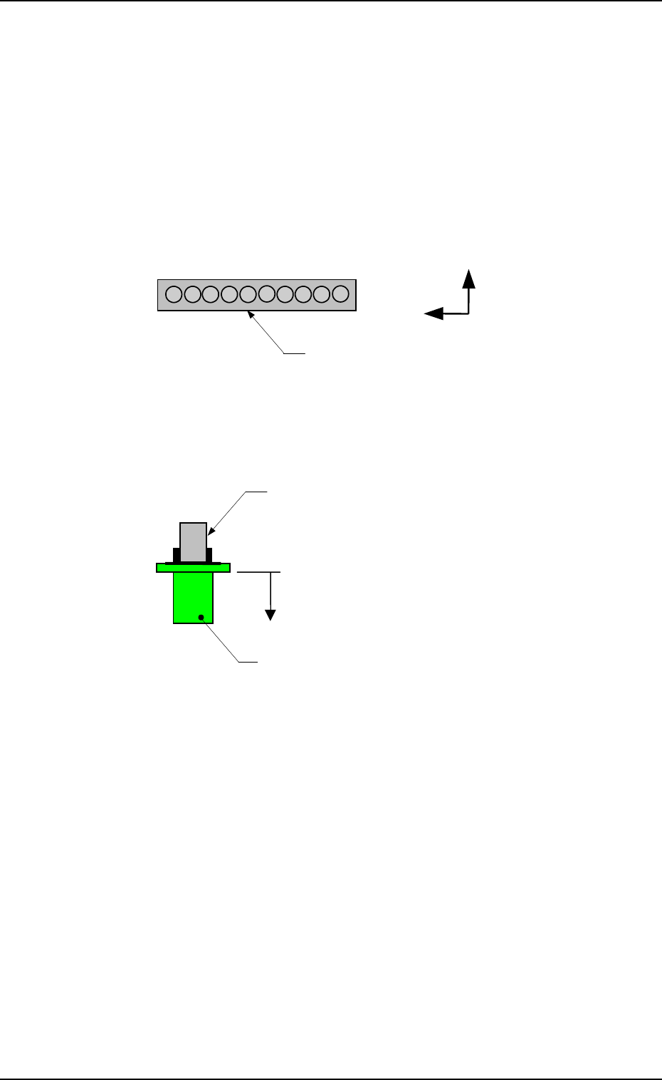
Set the values which represent the positional deviations of Nozzle Stocker
A1 based on Beam B.
X (Horizontal) and Y (Vertical)
When offset parameters are set with a plus (+) sign, the nozzle change
directions are changed to “X (+)” and “Y (+)” shown in the figure.
5-28
LEVEL (Height)
When an offset parameter is set with a plus (+) sign, the nozzle change
direction is changed to “L (+)” shown in the figure, concluding that the
descending stroke has increased.
SET LVL
Set an offset value (offset in vertical (height) direction of the head) re-
quired when a nozzle is attached to the head.
(This is added to the parameter in the “LEVEL (Height)” data box.)
When an offset parameter is set with a plus (+) sign, the up/down shaft
descends, concluding that the descending stroke has increased.
RESET LVL
Set an offset value (offset in vertical (height) direction of the head) re-
quired when the nozzle is stored.
(This is added to the parameter in the “LEVEL (Height)” data box.)
When an offset parameter is set with a plus (+) sign, the up/down shaft
descends, concluding that the descending stroke has increased.
Note: As for the values to be set in the “X” and “Y” data boxes, align the
nozzle position manually at several places (1 through 10) and per-
form the measurement. Then, set the mean values in each data box.
When the nozzle is manually aligned only at one place, it may be
positioned at a place where the nozzle cannot be changed easily.
Fig. 2E73
Fig. 2E74
Nozzle Stocker A1
1
10
Y(+)
X(+)
L(+)
Nozzle
Nozzle Clamp Section