2OM-1011-002.pdf - 第231页
0305-001 Tg0858-PM-PM BEAM A HEAD #2 CAM-A2 X (Horizontal), (V ertical) These offset parameters indicate the positional deviations of the head rotational center compared with the center of Camera A2 when Head #2 on Beam …
0305-001 Tg0858-PM-PM
BEAM A HEAD #1
CAM-A1 X (Horizontal), Y (Vertical)
These offset parameters indicate the positional deviations
of the head rotational center compared with the center of
Camera A1 when Head #1 on Beam A faces Camera A1 as
a subordinate head. The parameters are set based on the
camera scanning coordinate system of the component rec-
ognition camera.
CAM-B2 X (Horizontal), Y (Vertical)
These offset parameters indicate the positional deviations
of the head rotational center compared with the center of
Camera B2 when Head #1 on Beam A faces Camera B2 as
a subordinate head. The parameters are set based on the
camera scanning coordinate system of the component rec-
ognition camera.
5-49
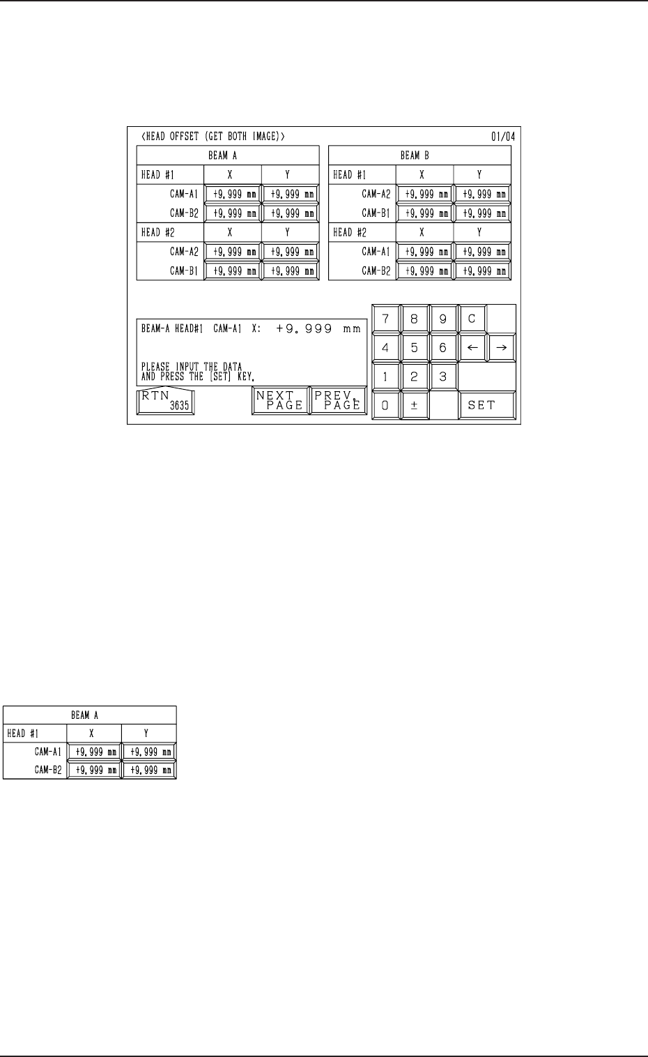
16. HEAD OFFSET (GET BOTH IMAGE) Display
16. HEAD OFFSET (GET BOTH IMAGE) Display
When the [HEAD OFFSET (GET BOTH IMAGE)] key is pressed at the “OFF-
SET DATA” display, the following display appears on the screen.
Fig. 2E118
When steps are paired through the simultaneous pick-up or the pick-up prior-
ity function designated in the placement data, the component recognition func-
tion (simultaneous recognition function) is implemented with components be-
ing picked up by both right and left heads. At this time, this offset data indi-
cates where the head rotational center of the subordinate head is located in
comparison with the center of the confronting camera.
When each head on both Beams A and B is used as a subordinate one, the
positional deviations between the center of each head and the centers of the
confronting cameras are determined and set.
These groups of all offset parameters are automatically calculated through teach-
ing operations.
Fig. 2E119
0305-001 Tg0858-PM-PM
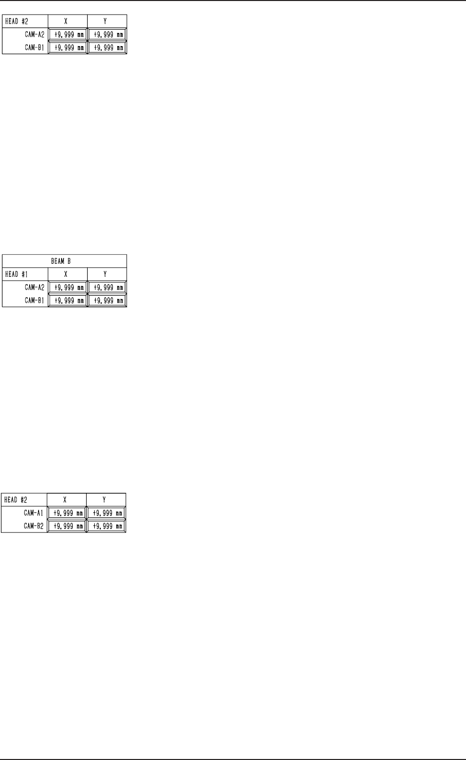
BEAM A HEAD #2
CAM-A2 X (Horizontal), (Vertical)
These offset parameters indicate the positional deviations
of the head rotational center compared with the center of
Camera A2 when Head #2 on Beam A faces Camera A2 as
a subordinate head. The parameters are set based on the
camera scanning coordinate system of the component rec-
ognition camera.
CAM-B1 X (Horizontal), (Vertical)
These offset parameters indicate the positional deviations
of the head rotational center compared with the center of
Camera B1 when Head #2 on Beam A faces Camera B1 as
a subordinate head. The parameters are set based on the
camera scanning coordinate system of the component rec-
ognition camera.
BEAM B HEAD #1
CAM-A2 X (Horizontal), Y (Vertical)
These offset parameters indicate the positional deviations
of the head rotational center compared with the center of
Camera A2 when Head #1 on Beam B faces Camera A2 as
a subordinate head. The parameters are set based on the
camera scanning coordinate system of the component rec-
ognition camera.
CAM-B1 X (Horizontal), Y (Vertical)
These offset parameters indicate the positional deviations
of the head rotational center compared with the center of
Camera B1 when Head #1 on Beam B faces Camera B1 as a
subordinate head. The parameters are set based on the cam-
era scanning coordinate system of the component recogni-
tion camera.
BEAM B HEAD #2
CAM-A1 X (Horizontal), (Vertical)
These offset parameters indicate the positional deviations
of the head rotational center compared with the center of
Camera A1 when Head #2 on Beam B faces Camera A1 as
a subordinate head. The parameters are set based on the
camera scanning coordinate system of the component rec-
ognition camera.
CAM-B2 X (Horizontal), (Vertical)
These offset parameters indicate the positional deviations
of the head rotational center compared with the center of
Camera B2 when Head #2 on Beam B faces Camera B2 as a
subordinate head. The parameters are set based on the cam-
era scanning coordinate system of the component recogni-
tion camera.
5-50
16. HEAD OFFSET (GET BOTH IMAGE) Display
Fig. 2E120
Fig. 2E121
Fig. 2E122

0305-001 Tg0858-PM-PM5-51
16. HEAD OFFSET (GET BOTH IMAGE) Display
Reference
Subordinate Head:
When two steps are paired through the simultaneous pick-up or the pick-up priority func-
tion designated in the placement data, this head handles the component related to the step
No. larger than the other.
On the other hand, the head which handles the component related to the smaller step No. is
called “Guide Head”.
The simultaneous recognition is automatically prohibited and images are captured indi-
vidually when,
•
components which require BGA lighting are picked up.
•
a value other than “0” (zero) is set (designation of eccentric pick-up) in the “X” and “Y”
data boxes of the label “PICK-UP LOCATION CORRECTION” at the “CMPNT LI-
BRARY” display.
•
The visual field of the confronting camera cannot cover the components picked up by
the right and left heads.
In this case, the beams must be moved such that the rotational centers of the heads are lo-
cated at the camera centers before the images are captured.
Compared with this, in the case of the simultaneous recognition, the guide head (for the
smaller step) moves normally but the subordinate head faces the other one at the position
where the head rotational center does not match the camera center due to the relation be-
tween the head-to-head and camera-to-camera pitches. Therefore, this offset data is re-
quired for recognition processing and correction calculation.