2OM-1011-002.pdf - 第78页
0305-001 Tg0858-PM-PM • T o designate the pick-up priority (“2” to be set as “S” data) Designation Possible Designation Impossible • Pairing of Com ponents between T ape Feed ers • Pairing of Com ponents between T ape an…
0305-001 Tg0858-PM-PM
• To designate the simultaneous pick-up (“1” to be set as “S” data)
2-58
2.6 Placement Data
Table 2B6

0305-001 Tg0858-PM-PM
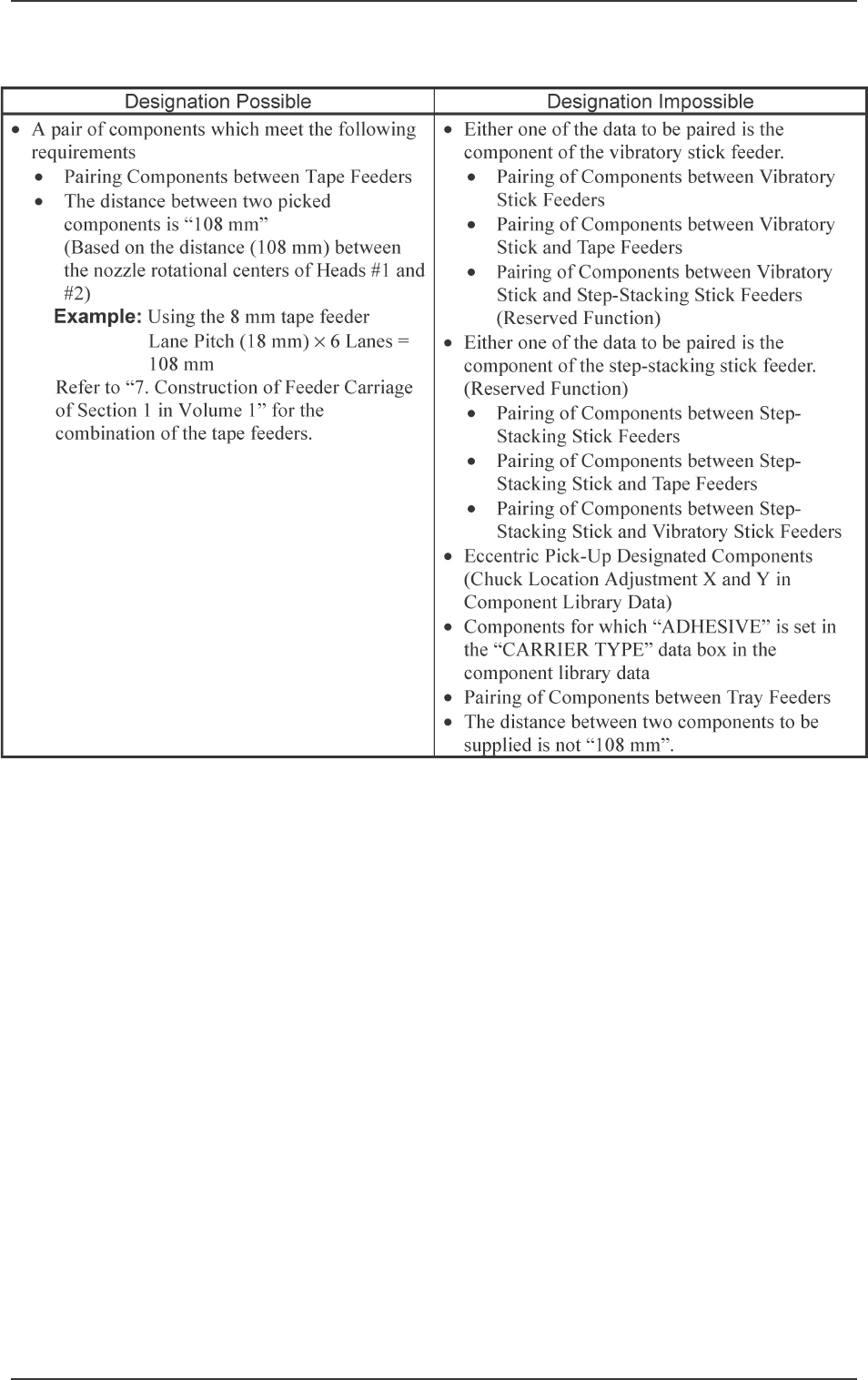
• To designate the pick-up priority (“2” to be set as “S” data)
Designation Possible Designation Impossible
•
Pairing of Components between Tape Feeders
•
Pairing of Components between Tape and
Vibratory Stick Feeders
•
Pairing of Components between Tape and
Step-Stacking Stick Feeders (Reserved
Function)
•
Pairing of Components between Tape and Tray
Feeders (Only Beam A Side)
•
Pairing of Components between Vibratory Stick
Feeders
•
Pairing of Components between Vibratory Stick
and Step-Stacking Stick Feeders (Reserved
Function)
•
Pairing of Components between Vibratory Stick
and Tray Feeders (Only Beam A Side)
•
Pairing of Components between Step-Stacking
Stick Feeders (Reserved Function)
•
Pairing of Components between Step-Stacking
Stick and Tray Feeders (Only Beam A Side)
(Reserved Function)
•
Pairing of Components between Tray Feeders
(Only Beam A Side)
•
Eccentric Pick-Up Designated Components
(Chuck Location Adjustment X and Y in
Component Library Data)
•
Components for which “ADHESIVE” is set in
the “CARRIER TYPE” data box in the
component library data
•
Both components belong to the same area where
only one head can pick them up.
(Such components cannot be picked up by the
counteractive head because only the left head
can be used for the 6 lanes at the left end and
only the right head for the 6 lanes at the right
end.)
•
Pairing of a component located at one side of the
X/Y beam and a component at the other side
2.6 Placement Data
2-59
Table 2B7

0305-001 Tg0858-PM-PM
V
[Setting of Repetitive Patterns]
When multi-unit P.C.B.’s (repetitive patterns) are used and the P.E.C. rec-
ognition function is implemented on each unit P.C.B., set “01” or “02” in the
text field labeled “V” of P-0000 step.
00: B.B.R. P.E.C. Recognition Function “OFF”
01: B.B.R. P.E.C. Recognition Function “ON” (1-Point Recognition)
02: B.B.R. P.E.C. Recognition Function “ON” (2-Point Recognition)
• When a recognition mode is specified, the coordinates of mark position
and mark data can be set in the V-0000 step of the placement data (V).
Ref.: As both V data shown at the placement data (P) and (V) displays
are the same, the V data can be entered at either display.
[Setting of Each Individual Placement Points]
Set each individual placement points in the text field labeled “V” of the
placement step.
00: P.E.C. Recognition “OFF”
01: P.E.C. Recognition “ON” (1-Point Recognition)
02: P.E.C. Recognition “ON” (2-Point Recognition)
Note: Set “ON” in the “P.E.C. RECOGNITION” data box and in the “LO-
CAL” data box of the label “P.E.C. RECOGNITION MODE” at the
“OPERATION DATA” display.
Setting the Beam Mediation
For beam mediation, set “1*” or “2*” in the text field of the V data (tens
digit) for P-0000 step.
The beam mediation function makes the beam remain as it is until another
beam occupies the placement area, when the placement area is empty after
the component recognition is completed.
0*: Beam Mediation not performed
1*: Beam Mediation always performed
2*: Beam Mediation performed, except in the case of exceptional pro-
cessing such as recovery action.
Ref.: In the case that there is any remarkable difference between each of
the placement points obtained by Beam A and Beam B, the setting
of “1*” will allow a shorter PCB finishing time.
2.6 Placement Data
2-60