2OM-1011-002.pdf - 第166页
0305-001 Tg0858-PM-PM Pilot Stopper Action Mode This sets the change of the pilot stopper action when the al- ready placed P .C.B. is output from the positioning section. [ST ANDARD] : The pilot stopper is lowered and P …
0305-001 Tg0858-PM-PM
OUTPUT CONVEYOR TIMER #2
The operating time of the output conveyor can be limited by
this timer when a P.C.B. is transferred inside the machine by
the output conveyor.
This timer measures the operating time of the output conveyor
and is used to detect an interrupted P.C.B.
Note: This time is also used for the timer of EL/ER conveyor
(option).
• Data Input Range:
0 to 99 seconds
Note: When “STANDARD” is set in the “OUTPUT MODE”
data box, the machine stops in an error condition after
this timer has reached the set time.
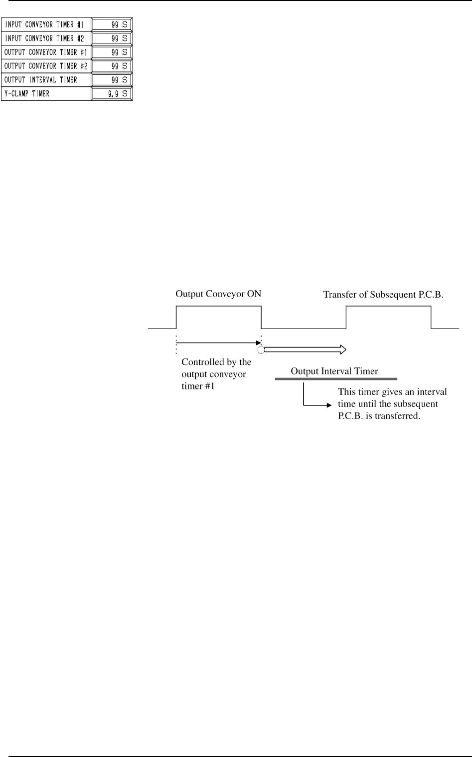
OUTPUT INTERVAL TIMER
When “INTERVAL” (P.C.B. output without handshaking) is
set in the “OUTPUT MODE” data box, this timer is used to
set an output interval time.
• Data Input Range: 0 to 99 seconds
2. P.C.B. TRANSFER MODE SET-UP Display
3-10
Fig. 2C21
Y-CLAMP TIMER
Set a period of time during which the Y pusher moves forward
or backward for P.C.B. alignment in Y direction (horizontal
P.C.B. positioning). The set parameter is used commonly for
both forward and backward movements.
The Y pusher is not provided with any sensors for detection of
the forward or backward movement because the Y pusher
moves only a short distance. Therefore, the timing of move-
ment is controlled by the software-based timer.
• Default: 0.3 seconds
• Enter a period of time during which the Y alignment is
made completely.
• Whenever the speed of the forward or the backward move-
ment is adjusted, it is required to change the set parameter
to avoid any impact which may be given to a P.C.B. dur-
ing Y alignment.
• Data Input Range: 0 to 99 seconds
Note: When the parameter is too large, excessively long
time will be required for P.C.B. positioning or re-
leasing.
Fig. 2C20

0305-001 Tg0858-PM-PM
Pilot Stopper Action Mode
This sets the change of the pilot stopper action when the al-
ready placed P.C.B. is output from the positioning section.
[STANDARD] : The pilot stopper is lowered and P conveyor
and R conveyor are turned normally to output
the P.C.B.
[EXIT POS] : This setting prevents the pilot stopper from
rising until the P.C.B. detection photosensor
has detected the P.C.B., so that the pilot stop
per does not push up the P.C.B.
Pilot Stopper Position
Sets the P.C.B. stopper position when the components are
placed.
[STANDARD] : The stopper is operated in normal se
quence, as follows.
P.C.B. Clamp - Placement - Stopper Down -
Output
[LOW. POS] : The P.C.B. stopper is moved to the low
est position during the component place
ment. It operates as follows:
P.C.B. Clamp - Stopper Down - Place
ment - Output
3-11
2. P.C.B. TRANSFER MODE SET-UP Display
Fig. 2C22
0305-001 Tg0858-PM-PM
Fig. 2C23
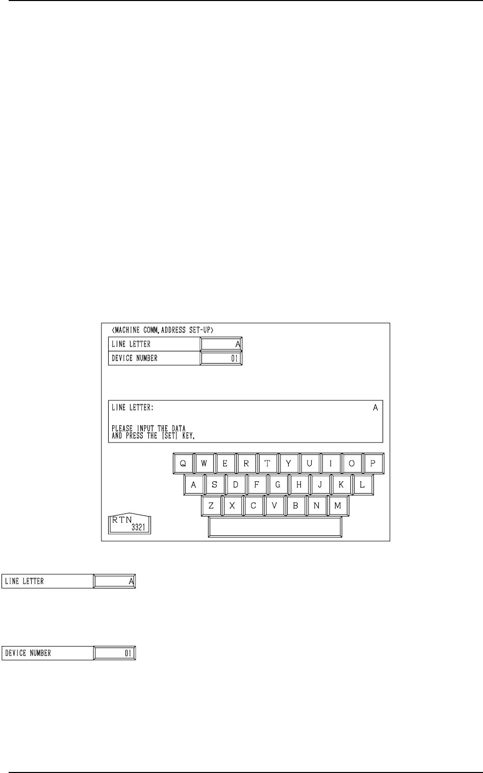
LINE LETTER
Set a line letter (interface address to the programming device
(option)) in the component placement system.
• Data Input Range: A to Z (Internal Data: ASCII)
DEVICE NUMBER
Set a device number in the component placement system line.
This data is used to identify the object machine when several
machines (same models) are assembled, forming one system
line.
(Interface Address to Programming Device)
• Data Input Range: 01 to 26 (Internal Data: ASCII “A to Z”)
3. MACHINE COMM. ADDRESS SET-UP Display
3-12
3. MACHINE COMM. ADDRESS SET-UP Display
When data is exchanged between a machine and an external device such as a
programming device (option), it is required to specify the machine (line letter
and device No.).
*1 When a component placement system line is constructed, it is advisable
that a common line letter be used in one system (combination of input,
main, and output machines).
*2 “Device Number” is an address data used to identify the object machine
when there is another machine of the same type in the same line.
Notes: (a) When data is exchanged between the main machine and the pro-
gramming device (option), the same line letter must be entered on
the programming device side.
(b) Even if a machine address data is changed, machine operation
remains unchanged. However, if an address data is changed after
each offset data for the machine is stored in the programming
device, the offset data may not be reloaded to the machine.
When the [MACHINE COMM. ADDRESS SET-UP] key is pressed at the
“DEVICE DATA” display, the following display appears on the screen.
Fig. 2C24
Fig. 2C25